10
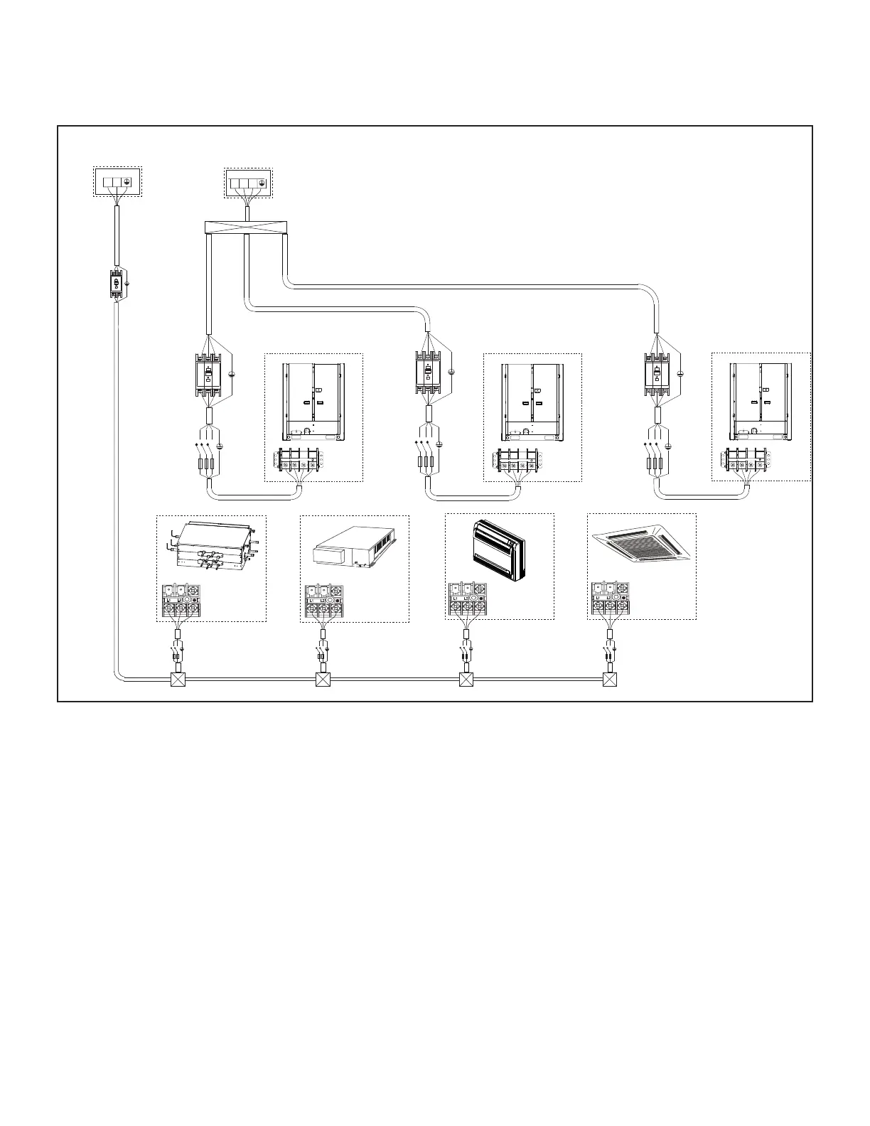
Figure 12. Typical Power Wiring Diagram (VRF Heat Recovery System Shown)
L2 L3L1
L2L1
208/230V 3Ph 60Hz
or 460V 3Ph 60Hz
Power supply
208/230V 1Ph 60Hz
Power supply
Mode Selection Box Indoor unit
Indoor unit Indoor unit
Dedicated
breaker
Service
Disconnect
L1 L2
L1 L2
Fuse
Service
Disconnect
L1 L2
Fuse
Service
Disconnect
L1 L2
Fuse
Service
Disconnect
L1 L2
Fuse
Outdoor Unit (Main Unit)
L1 L2 L3
Outdoor Unit (Sub1 unit)
L1 L2 L3
Outdoor Unit(Sub2 Unit)
L1 L2 L3
L1 L2 L3
L1 L2 L3
L1 L2 L3
L1 L2 L3
L1 L2 L3
L1 L2 L3
Service
Disconnect
Service
Disconnect
Service
Disconnect
Indoor units and mode selection boxes on the same
refrigeration circuit should have a common power supply
but must have an independent disconnect switch installed
adjacent to each item of equipment for servicing and
maintenance purposes. Indoor unit and mode selection
box power supply MUST not be taken from the outdoor
unit. Always follow NEC/CEC and Local Codes.
 Loading...