2
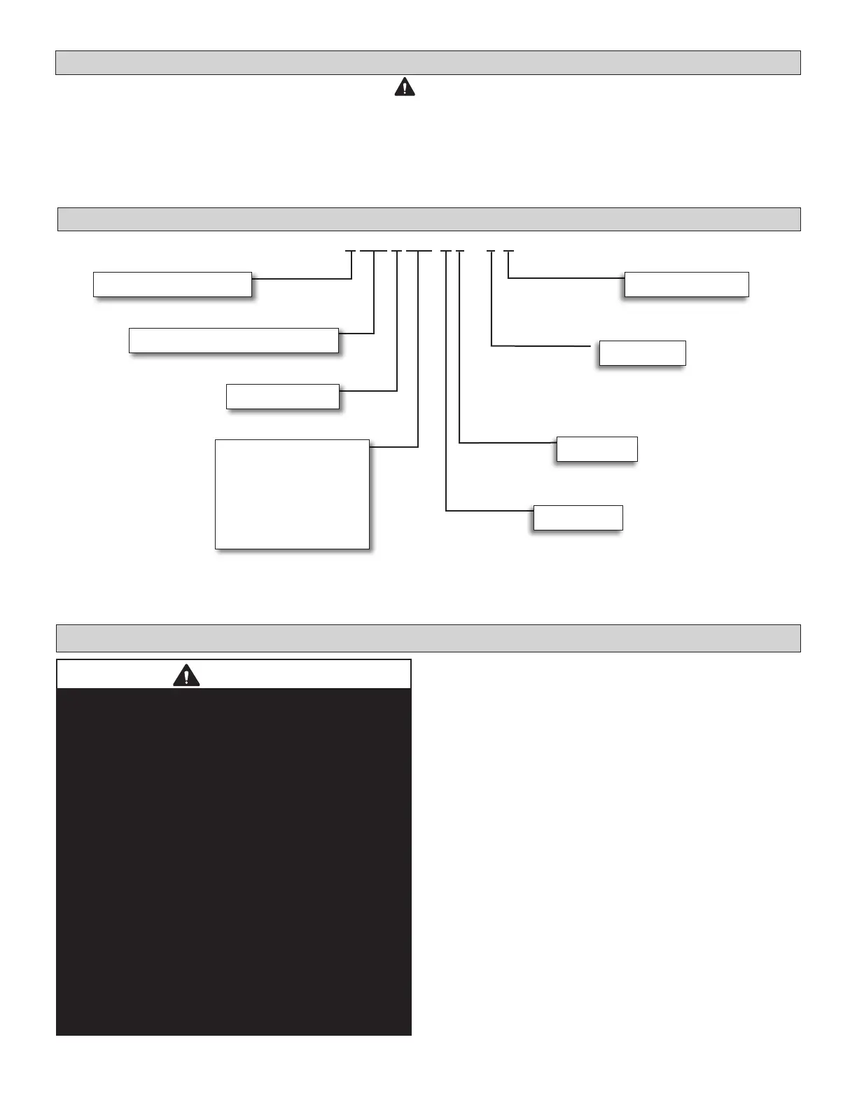
V WM B 012 H 4 - 3 P
Brand/Family
V = Variable Refrigerant Flow (VRF)
Unit Type
WM = Wall Mounted Non-Ducted Indoor Models
Major Design Sequence
B = 2nd Generation
Cooling Eciency
H = High Eciency
Refrigerant Type
4 = R-410A
Controls Protocol
3 = Phase 3
Nominal Cooling Capacity - Btuh
007 = 7,000 Btuh
009 = 9,000 Btuh
012 = 12,000 Btuh
015 = 15,000 Btuh
018 = 18,000 Btuh
024 = 24,000 Btuh
030 = 30,000 Btuh
Voltage
P = 208/230V-1 phase-60hz
Model Number Identication
Safety Requirements
System Piping
NOTE - Only Lennox VRF indoor units will work with Lennox VRF outdoor units and associated mechanical
equipment. Lennox Mini Split indoor units are similar in appearance but must not be connected to a Lennox VRF
refrigerant circuit. Please refer to model numbers to conrm compatibility. Model numbers for Lennox VRF units
start with a “V” and model numbers for Lennox Mini-Splits start with a “M”.
ELECTRICAL SHOCK, FIRE, OR EXPLOSION HAZARD.
Do not touch the unit or the controller if your hands are wet.
DO NOT spray water on the indoor unit for any reason.
Do not replace a fuse with a fuse of a dierent rating. Do not use a jumper wire to replace a fuse. Do not insert
your hands, tools or any other item into the air intake or air outlet at either the indoor or outdoor unit.
Do not allow children to operate the system.
WARNING
CAUTION
VRF system piping is customized for each installation.
The LVSS (Lennox VRF Selection Software) piping
report is an engineered design that must be followed.
The piping diagram or diagrams included within the LVSS
report have been prepared based on the information
provided to the Lennox VRF applications department.
When the indicated lengths change from the gures
stated within the report, it is imperative that prior to the
commencement of the refrigerant pipe work installation,
Lennox VRF applications department are informed of
these proposed changes.
Upon receipt of this new information the Lennox VRF
applications department will conrm any changes that
may be applicable to this installation. If changes are
required, a new piping diagram will be produced and
will supersede all other previously provided documents.
Failure to provide this information regarding changes
to the original design may lead to insucient capacity,
equipment failure, warranty being made void and the
refusal to commission the system.
 Loading...