12
(PQ)
(PQ)
Outdoor unit
(main unit)
Outdoor unit
(sub1 unit)
Outdoor unit
(sub2 unit)
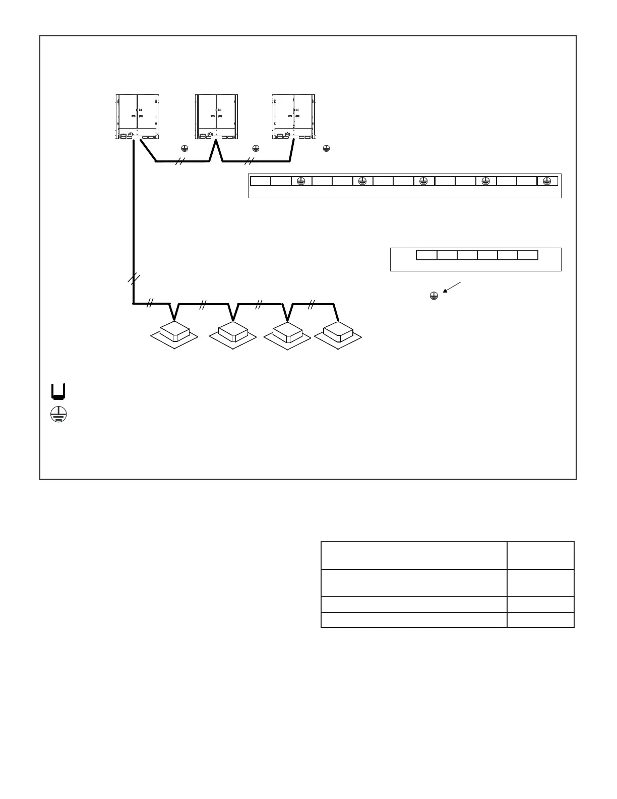
Install a terminating resistor (Ω120) at the last indoor unit terminals P and Q of the daisy chain.
P Q
All shields of shielded cable connect to
chassis GROUND terminal at Indoor Units. .
18 GA., stranded, 2-conductor, shielded control wire (polarity sensitive).
Typical Wiring Diagram, NEC/CEC and Local Codes apply.
(H1 H2 )
Outdoor Unit Communication Terminal Block
P Q H1 H2X YO AK1 K2
(H1 H2 )
(H1 H2 )
Indoor Unit Communication Terminal Block
HA HB 12V COM P Q
Ground cable shield
to Indoor Unit chassis
Figure 14. Typical Communication Wiring Diagram (VRF Heat Pump System)
NOTE – PQE Communication wiring is daisy-chained from the outdoor unit to each indoor unit in one continuous run.
Tightening torque for the terminal screws
• Use the correct screwdriver for ghting the terminal
screws. If the screwdriver blade is too small, the head
of the screw might be damaged, and the screw will
not be properly tightened.
• If the terminal screws are over tightened, screws
might be damaged.
• Refer to the table below for the tightening torque of
the terminal screws.
• After wiring, conrm all connections are correct; Then
turn on power supply to the unit.
Table 4. Terminal Screw Tightening Torque
Tightening
torque (lb-ft)
Terminal base of remote controller/
Signal transmission wire (X2M)
0.58-0.72
Terminal base of power supply (X1M) 0.87-1.06
Grounding terminal (M4) 1.06-1.43
 Loading...