Page 7
1
2
3
4
SUCTION
POCKET
SUCTION
ORBITING SCROLL
STATIONARY SCROLL
SUCTION
SUCTION
DISCHARGE
POCKET
SUCTION
INTERMEDIATE PRESSURE
GAS
CRESCENT
SHAPED
GAS POCKET
HIGH PRESSURE GAS
FLANKS SEALED
BY CENTRIFUGAL
FORCE
MOVEMENT OF ORBIT
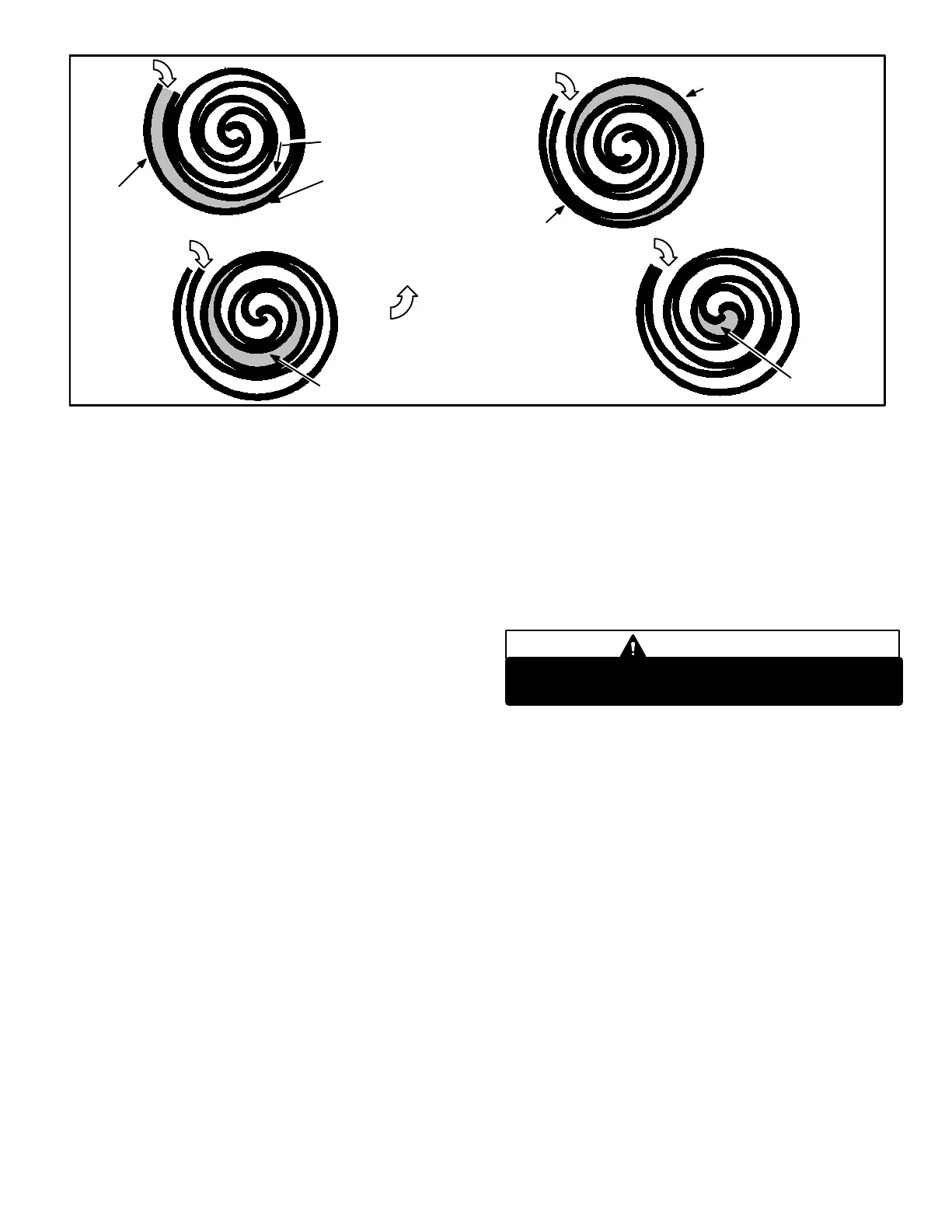
FIGURE 8
The counterclockwise orbiting scroll draws gas into the outer
crescent shaped gas pocket created by the two scrolls (figure 8
− 1). The centrifugal action of the orbiting scroll seals off the
flanks of the scrolls (figure 8 − 2). As the orbiting motion contin-
ues, the gas is forced toward the center of the scroll and the gas
pocket becomes compressed (figure 8 − 3). When the com-
pressed gas reaches the center, it is discharged vertically into a
chamber and discharge port in the top of the compressor (figure
6). The discharge pressure forcing down on the top scroll helps
seal off the upper and lower edges (tips) of the scrolls (figure 6).
During a single orbit, several pockets of gas are compressed
simultaneously providing smooth continuous compression.
The scroll compressor is tolerant to the effects of liquid return. If
liquid enters the scrolls, the orbiting scroll is allowed to separate
from the stationary scroll. The liquid is worked toward the center
of the scroll and is discharged. If the compressor is replaced,
conventional Lennox cleanup practices must be used.
Due to its efficiency, the scroll compressor is capable of draw-
ing a much deeper vacuum than reciprocating compressors.
Deep vacuum operation can cause internal fusite arcing
resulting in damaged internal parts and will result in com-
pressor failure. Never use a scroll compressor for eva-
cuating or pumping−down" the system. This type of dam-
age can be detected and will result in denial of warranty
claims.
The scroll compressor is quieter than a reciprocating com-
pressor, however, the two compressors have much different
sound characteristics. The sounds made by a scroll compres-
sor do not affect system reliability, performance, or indicate
damage.
C − Drier
A filter drier designed for all XC14 model units must be
installed in the liquid line. The field installed drier is designed
to remove moisture, which can lead to compressor failure.
Any time unit is exposed to open air due to service, drier
must be replaced. All replacement driers must be ap-
proved for R410A refrigerant.
D − Condenser Fan Motor (B4)
Make sure all power is disconnected before
beginning electrical service procedures.
DANGER
All units use single−phase PSC fan motors which require a run
capacitor. In all units, the condenser fan is controlled by
the compressor contactor.
ELECTRICAL DATA tables in this manual show specifi-
cations for condenser fans used in XC14’s.
Access to the condenser fan motor on all units is gained
by removing the four screws securing the fan assembly.
See figure 9. The grill fan assembly can be removed from
the cabinet as one piece. See figure 10. The condenser
fan motor is removed from the fan guard by removing the
four nuts found on top of the grill. See figure 10 if con-
denser fan motor replacement is necessary.
 Loading...