Page 16
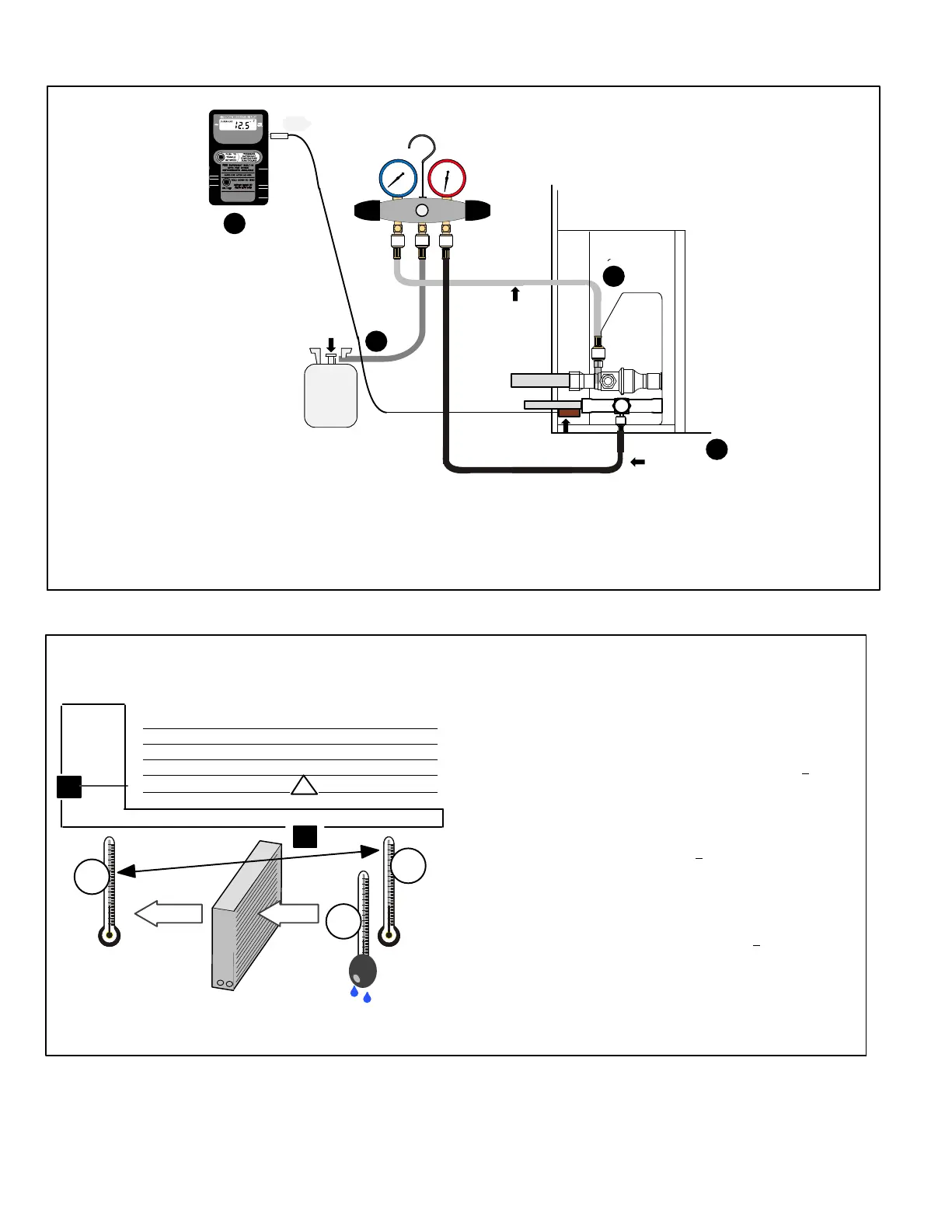
D − Charging 018, 024 −2 units & 030 through 060 −3 units
TO SUCTION
SERVICE VALVE
TO LIQUID
LINE SERVICE
VALVE
TEMPERATURE
SENSOR
QC RESTRICTOR
FITTING
REFRIGERANT
TANK
TEMPERATURE SENSOR
(LIQUID LINE)
MANIFOLD
GAUGE SET
A Close manifold gauge set valves and connect the center hose to an upright cylinder of R−410A.
B Connect the manifold gauge set’s low pressure side to the suction line service port.
C Connect the manifold gauge set’s high pressure side to the liquid line service port.
D Position temperature sensor on liquid line near liquid line service port.
OUTDOOR UNIT
CHARGING SYSTEM
A
B
C
D
FIGURE 17
1. Determine the desired DTMeasure entering air temperature
using dry bulb (A) and wet bulb (B). DT is the intersecting value of A
and B in the table (see triangle).
2. Find temperature drop across coilMeasure the coil’s dry bulb
entering and leaving air temperatures (A and C). Temperature Drop
Formula: (T
Drop
) = A minus C.
3. Determine if fan needs adjustmentIf the difference between
the measured T
Drop
and the desired DT (T
Drop
–DT) is within +3º, no
adjustment is needed. See examples: Assume DT = 15 and A temp.
= 72º, these C temperatures would necessitate stated actions:
Cº T
Drop
– DT = ºF ACTION
53º 19 – 15 = 4 Increase the airflow
58º 14 – 15 = −1 (within +
3º range) no change
62º 10 – 15 = −5 Decrease the airflow
4. Adjust the fan speedSee indoor unit instructions to
increase/decrease fan speed.
Changing air flow affects all temperatures; recheck temperatures to
confirm that the temperature drop and DT are within +
3º.
DT
80 24 24 24 23 23 22 22 22 20 19 18 17 16 15
78 23 23 23 22 22 21 21 20 19 18 17 16 15 14
76 22 22 22 21 21 20 19 19 18 17 16 15 14 13
74 21 21 21 20 19 19 18 17 16 16 15 14 13 12
72 20 20 19 18 17 17 16 15 15 14 13 12 11 10
70 19 19 18 18 17 17 16 15 15 14 13 12 11 10
57 58 59 60 61 62 63 64 65 66 67 68 69 70
Temp.
of air
entering
indoor
coil ºF
INDOOR
COIL
DRY BULBDRY
BULB
WET
BULB
B
T
Drop
19º
A
Dry−bulb
Wet−bulb ºF
A
72º
B
64º
C
53º
air flowair flow
All temperatures are
expressed in ºF
INDOOR COIL AIRFLOW CHECK
Check indoor coil airflow using the Delta−T (
DT) process as illustrated.
FIGURE 18
 Loading...