Page 9
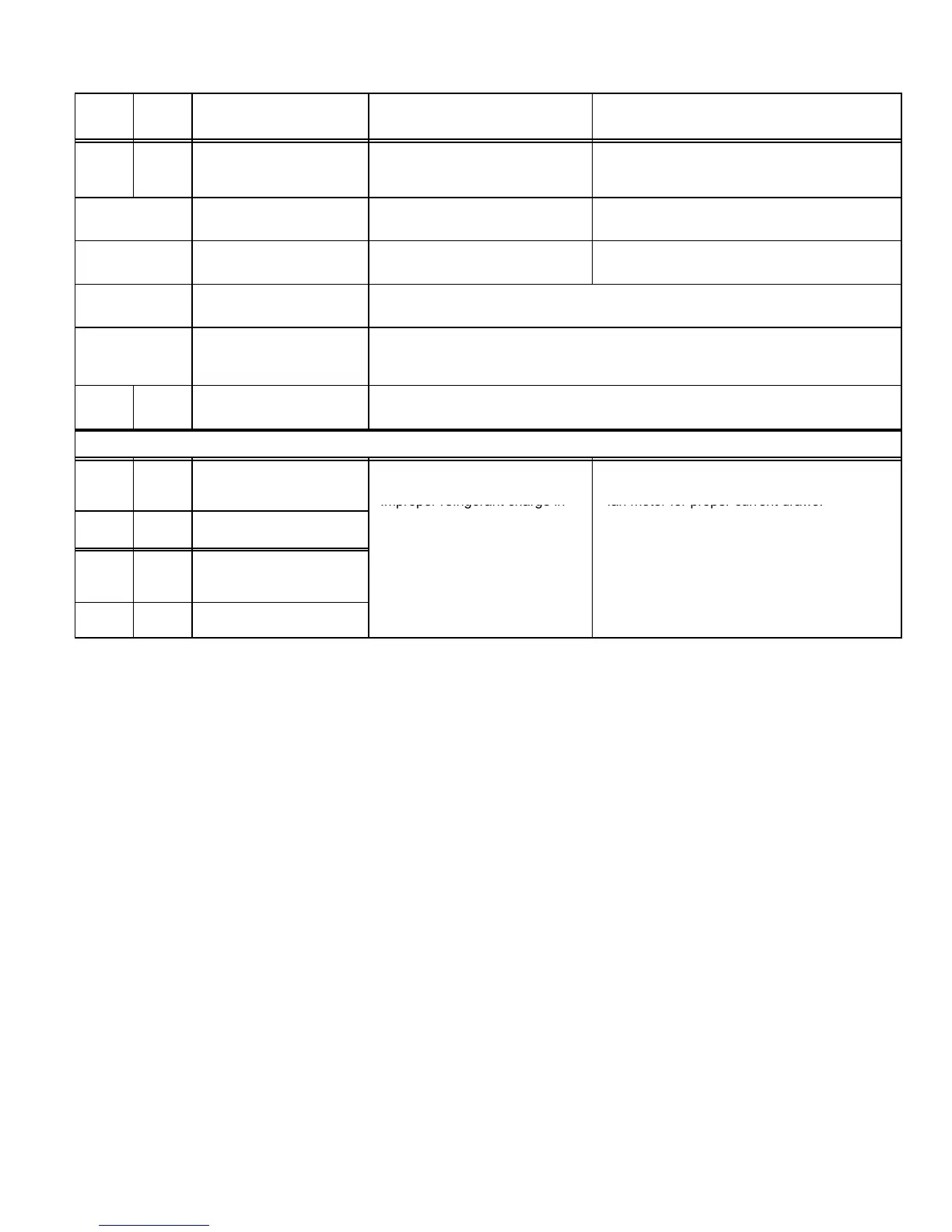
TABLE 2
Diagnostic Fault Code
DS2
Green
DS1
Red
Condition/Code Possible Cause(s) Solution
OFF OFF Power problem No power (24V) to control termi-
nals R & C or board failure.
1
Check control transformer power (24V).
2
If power is available to control and LED(s) do
not light, replace board.
Simultaneous
SLOW Flash
Normal operation Unit operating normally or in
standby mode.
None required.
Alternating
SLOW Flash
5−minute anti−short cycle
delay
Initial power up, safety trip, end of
room thermostat demand.
None required (Jumper TEST pins to override)
Simultaneous
FAST Flash
Ambient Sensor Problem Sensor being detected open or shorted or out of temperature range. Control will
revert to time/temperature defrost operation. (System will still heat or cool).
Alternating
FAST Flash
Coil Sensor Problem Sensor being detected open or shorted or out of temperature range. Control will not
perform demand or time/temperature defrost operation. (System will still heat or
cool).
ON ON Circuit Board Failure Indicates that control has internal component failure. Cycle 24 volt power to control.
If code does not clear, replace control.
FAULT & LOCKOUT CODES (Each fault adds 1 strike to that code’s counter; 5 strikes per code = LOCKOUT)
OFF SLOW
Flash
Low Pressure Fault
1
Restricted air flow over indoor or
outdoor coil.
2
Improper refrigerant charge in
1
Remove any blockages or restrictions from
coils and/or fans. Check indoor and outdoor
fan motor for proper current draws.

 Loading...