Page 6
STEP 2 -- ELECTRICAL (Continued) -- Field Control Wiring
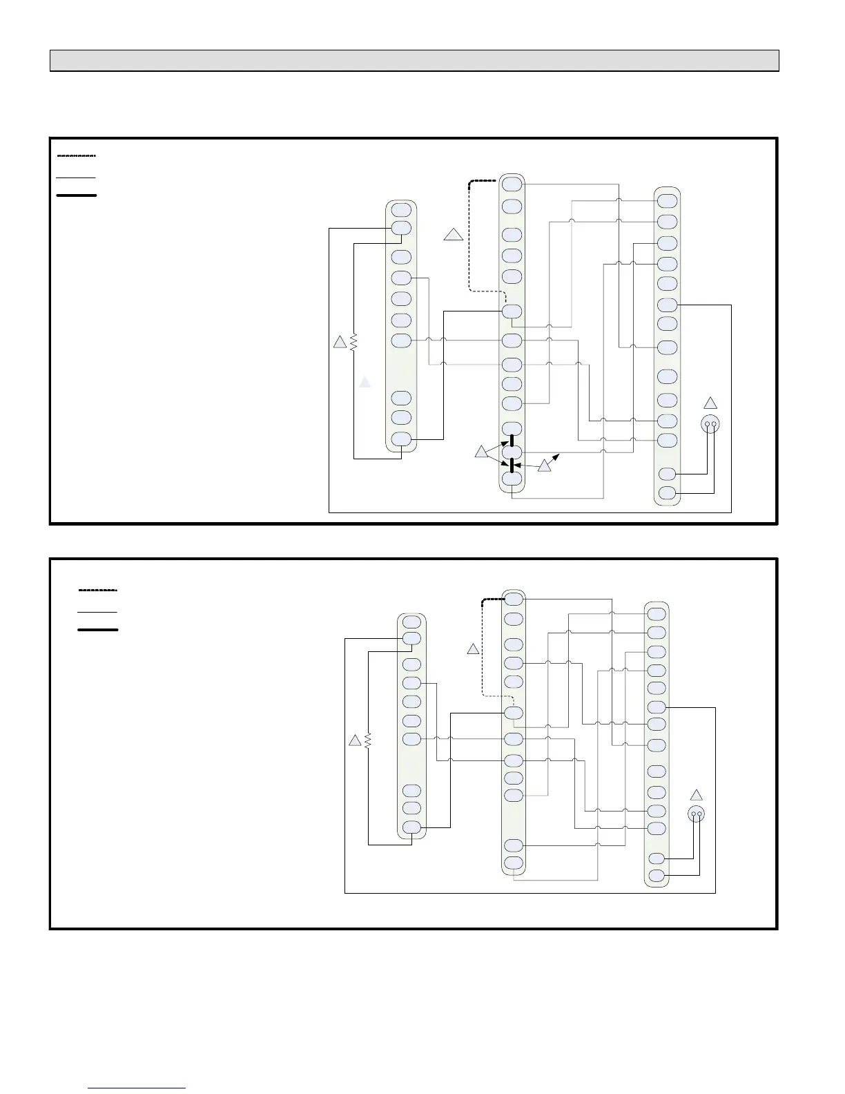
The following two illustrations provide examples of control wiring connections when using a non-communicating thermostat.
For examples of control wiring in complete or partial communicating systems, see the iComfortt-enabled thermostat
Quick Start Guide which is provided with the thermostat.
Y1
O
R
W1
G
D
R
Y1
L
C
C
Air Handler Control
ComfortSense[ 7000 Thermostats
Catalog # Y0349 or Y2081
Single−Stage
Air Conditioner Control
B
Y2
Y2
i−
W
O
i+
DS
L
T
T
W2
H
W3
H
O
C
L
Y2
DS
DH
G
R
Y1
W2
W1
1
2
5
On−board link
Low voltage thermostat wiring
Flat metal jumper
4
3
1. Thermostat T terminals are used for outdoor
sensor input. Use for thermostat's outdoor
temperature display (optional).
2. R to L connection is required for this model only
when used with the ComfortSense
®
7000
thermostat- (catalog number Y0349). Resistor Kit
(catalog number 47W97) required and ordered
separately.
3. Air handler control ships from factory with metal
jumpers (links) installed across W1, W2 and W3.
For single-stage electric heat, do not remove
factory-installed metal link.
4. Air handler control ships from factory with metal
jumpers installed across W1, W2 and W3. For
two-stage electric heat, cut factory-installed metal
link between W1 and W2. Then, connect
thermostat wire between the air handler control's
W2 and the thermostat's W2 terminal.
5. Cut on-board link (clippable wire) DS-R for
Humiditrol
®
or Harmony IIIt applications. This will
slow the indoor blower motor to the lowest speed
setting. See air handler installation instruction or
product specifications bulletin for lowest fan speed
information.
FIGURE 9
Y1
O
R
W1
G
D
R
Y1
L
C
C
Furnace Control
ComfortSense[ 7000 Thermostats
Catalog # Y0349 or Y2081
Single−Stage
Air Conditioner Control
B
Y2
Y2
i−
W
O
i+
DS
L
T
T
W2
H
H
O
C
L
Y2
DS
DH
G
R
Y1
W2
W1
Cut on-board link (W914) (clippable wire) from DS to R for dehumidification (Optional).
1
2
3
1. Thermostat T terminals are used for outdoor sen
sor input. Sensor provides input for thermostat's
outdoor temperature display (optional).
2. R to L connection is required for this model only
when used with the ComfortSense
®
7000 ther
mostat - (catalog number Y0349). Resistor Kit
(catalog number 47W97) is required and must be
ordered separately.
3. Cut on-board link (clippable wire) DS-R for Humi
ditrol
®
or Harmony IIIt applications. This will slow
the indoor blower motor to the lowest speed set
ting. See furnace installation instruction or prod
uct specification bulletin for lowest fan speed in
formation.
On−board link
Low voltage thermostat wiring
Flat metal jumper
FIGURE 10
 Loading...