Page 52
506601−01
HEAT PUMP
CONTROL (A175)
CONTROL BOX
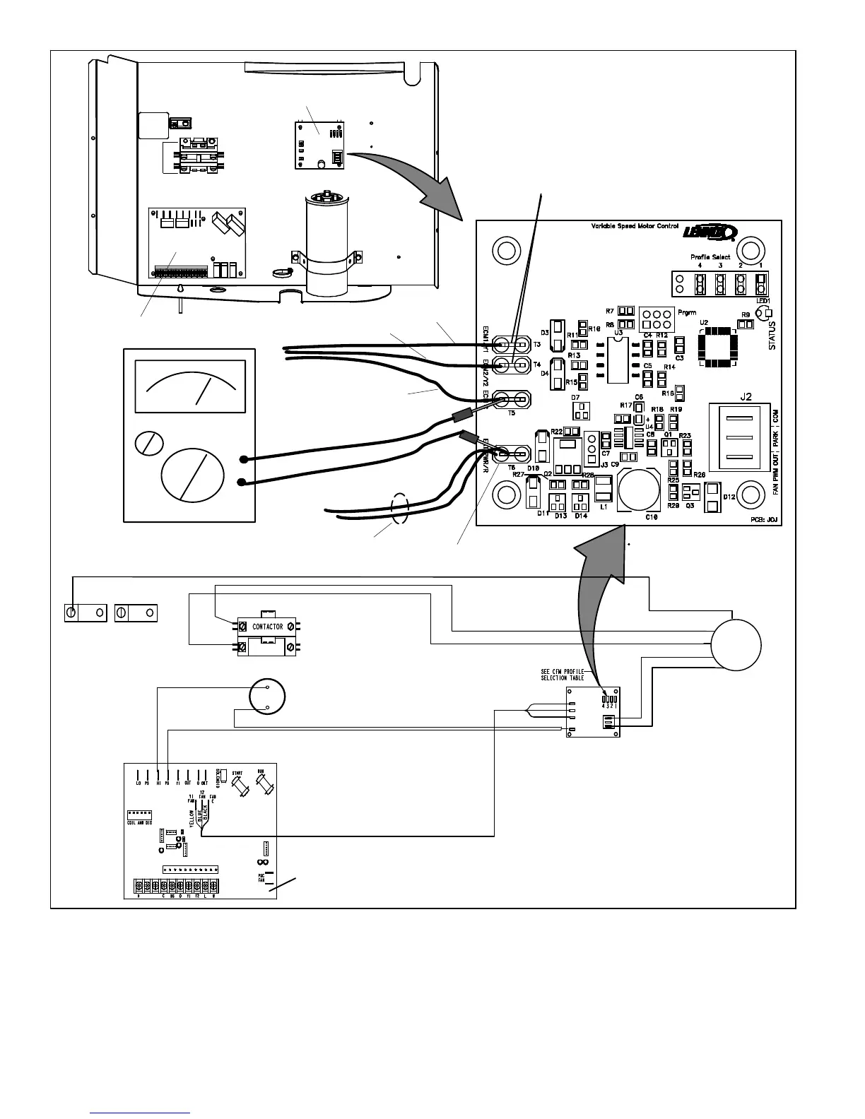
FAN MOTOR CONTROL (A177)
PULSE−WIDTH MODULATION (PWM)
ONE YELLOW WIRE FROM PS (E24) TERMINAL ON HEAT PUMP
CONTROL. AND SECOND YELLOW WIRES ON PIGGYBACK
TERMINALS GOES TO S4 HIGH PRESSURE SWITCH.
GREEN
RED
BROWN
RED
BLACK
RED
RED
GREEN
FAN MOTOR
CONTROL
YELLOW
BLACK
YELLOW
BLUE
SEE TABLE 15 FOR CFM PROFILE
SELECTION OPTIONS.
BLACK WIRE
YELLOW WIRE
VAC
VDC
24
EXT PWR/R (24VAC INPUT
DURING DEMAND ONLY)
INPUT VOLTAGES DURING DEMAND
ECM/Y1 ONLY − 24VDC
BOTH ECM/Y1 AND ECM/Y2 − 24VDC AT EACH INPUT
ECM/Y2 ONLY − 24VDC
BLUE WIRE
YELLOW
YELLOW
YELLOW
S4 HIGH PRESSURE SWITCH
YELLOW
HEAT PUMP CONTROL
B4 FAN
MOTOR
Figure 36. Testing for External Power to Fan Motor Control (A177)
 Loading...