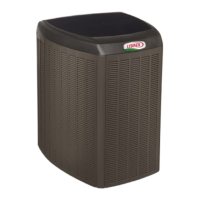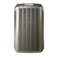
Do you have a question about the Lennox Signature XP21 Series and is the answer not in the manual?
| Type | Heat Pump |
|---|---|
| SEER Rating | Up to 21 |
| Refrigerant | R-410A |
| Cooling Capacity (BTU/h) | Up to 60, 000 |
| Heating Capacity (BTU/h) | Up to 60, 000 |
| Warranty | 10 years on compressor and parts |
| Cabinet | Galvanized steel with a powder-coated finish |
General introduction to unit components and identification.
Procedures for installing the unit, including placement and clearances.
Details on operating and servicing the unit, including controls and troubleshooting.
Explains how to identify unit model numbers and their components.
Lists technical specifications for various unit models.
Provides electrical characteristics and ratings for unit components.
Details the physical dimensions and clearance requirements of the unit.
Illustrates the location of major unit components and their connections.
Specifies torque values for proper fastener tightening during service.
Guidance on selecting and using manifold gauge sets for HVAC systems.
Instructions for operating the liquid and vapor line service valves.
Procedure for operating angle type service valves.
Procedure for operating ball type service valves.
Steps to access the service port for gauge connections.
Guidance on positioning the unit, considering sound and clearances.
Factors to consider when placing the unit for optimal performance.
Instructions for placing the unit on a foundation slab.
How to stabilize the unit on uneven surfaces using brackets.
Considerations for mounting the unit on a roof structure.
Details and diagrams for placing the unit outdoors.
Diagram illustrating slab mounting at ground level.
Visual guide for stabilizing the unit using mounting brackets.
Procedure for removing and installing access and louvered panels.
Information on installing or replacing refrigerant line sets.
How to install vertical refrigerant line runs.
Guidance for transitioning refrigerant line sets.
How to install horizontal refrigerant line runs.
Procedures for making brazed connections to service valves.
Connecting manifold gauge set for brazing operations.
Steps for brazing the refrigerant line set connections.
Procedures for flushing the refrigerant lines and indoor coil.
Procedure for installing a new check expansion valve.
Instructions for installing the sensing bulb correctly.
Procedure for installing the equalizer line.
Installing isolation grommets to protect refrigerant lines.
Procedure for testing the system for refrigerant leaks.
Detailed steps for performing a system leak test.
Procedures for evacuating the system to remove air and moisture.
Electrical installation requirements and codes.
Guidelines for installing the room thermostat.
ESD safety measures to protect electronic components.
Routing control wires for non-communicating systems.
Routing control wires for communicating systems.
Routing high voltage and ground wires.
Examples of control wiring for thermostats and air handlers.
Examples of control wiring for thermostats and furnaces.
Procedures for servicing units delivered without refrigerant.
Steps for starting the unit, including pre-start checks.
Procedures for testing and charging the system with refrigerant.
Procedures for adding or removing refrigerant for charging.
Checking indoor airflow in cooling mode using the Delta-T process.
Method for weighing in the initial refrigerant charge.
Method for verifying refrigerant charge using subcooling.
Lists indoor coil matchups and targeted subcooling values for charging.
Lists normal operating pressures for various conditions.
Details on the outdoor control unit, part number 101796-XX.
Jumpers and terminals for the heat pump control (A175).
Description of heat pump control jumpers and terminals.
Explains LED status, fault, and lockout codes for system diagnostics.
Procedures for resetting fault and lockout codes.
LED codes and related icomfort thermostat alert codes.
Continued list of LED codes and icomfort thermostat alert codes.
Compressor fault and alarm LED codes with related thermostat alerts.
Continued compressor fault and alarm LED codes.
Procedures for configuring and troubleshooting unit components.
Information on the fan motor control unit (A177).
Verifying fan motor control jumper settings for correct operation.
Fan motor speed settings, LED indicators, and DC voltage outputs.
Sequence for fan motor control LEDs indicating operational stages.
Visual guide to fan motor control, including wiring and testing.
Testing external power supply to the fan motor control.
Procedure for testing the operation of the fan motor.
Configuring unit capacity codes for the heat pump control.
Flowchart for configuring heat pump control capacity codes.
Using the multi-function test pins for various diagnostic tests.
Sequence for performing tests using the heat pump control's test pins.
Information on surge protection for the fan motor.
Information on surge protection for later fan motor models.
Details on jumper settings for the outdoor control unit.
Steps to configure the outdoor control unit for proper operation.
Auto-detection of unit type based on wiring connections.
Procedure for manually configuring the unit type and stages.
Setting unit capacity and outdoor fan profile.
Alert codes displayed on the seven-segment display.
Reconfiguring the outdoor control via the icomfort thermostat.
Detailed list of seven-segment display alert codes and causes.
Displays for outdoor control seven-segment unit status.
Continued list of outdoor control seven-segment unit status displays.
Field test and program menu options for the control.
Setting the outdoor fan speed profile.
Setting the unit capacity.
Information and testing procedures for compressors.
Details on the K4 compressor modulating solenoid.
Details on the K5 compressor modulating solenoid.
Testing the compressor internal solenoid.
Verifying the compressor solenoid coil has correct ohm values.
Verifying the DC output voltage at the solenoid plug.
Checklist for two-stage compressor field operational verification.
General overview, compressor protection features, and anti-short cycle delay.
Details on pressure switches and the defrost system operation.
Information on unit sensors including ambient, coil, and discharge temperature.
Explanation of how second-stage compressor operation works.
Explanation of the second-stage lock-in feature.
Sensor resistance data for ambient and coil sensors.
Sensor resistance data for the high discharge line sensor.
Adjusting top grille or fan motor mount for fan blade clearance.
Information on the crankcase heater and its function.
Components and operation of the reversing valve.
Maintenance procedures for the outdoor unit.
Maintenance procedures for the indoor unit.
Recommendations for areas with heavy snow or freezing rain.
Procedure to verify part- and full-load capacity of two-stage compressors.
Checklist for field operational verification of the XP21 unit.
Wiring diagram for XP21 model XP21-XXX-230-01.
Wiring diagrams for multiple XP21 models.
Wiring diagrams for various XP21 models.
Factory wiring diagram for XP21-XX-230-01 model.
Factory wiring diagrams for multiple XP21 models.
Factory wiring diagrams for various XP21 models.
Cooling sequence for specific outdoor control part number.
Cooling sequence for a different outdoor control part number.
Sequence of operation for the low pressure switch.
Sequence of operation for the high pressure switch.
Sequence of operation for the high discharge temperature sensor.
Sequences for defrost calibration and defrost modes.
Sequence of operation for W input faults or miswires.


 Loading...