Page 25
XP21
Y1
O
R
W1
G
D
R
Y1
L
C
C
Furnace Control
ComfortSense[ 7000 Thermostats
Catalog # Y0349 or Y2081
XP21 Two−Stage
Heat Pump Control
B
Y2
Y2
W
O
DS
L
T
T
W2
H
W3
H
O
C
L
Y2
DS
DH
G
R
Y1
W2
W1
1
2
3
4
6
5
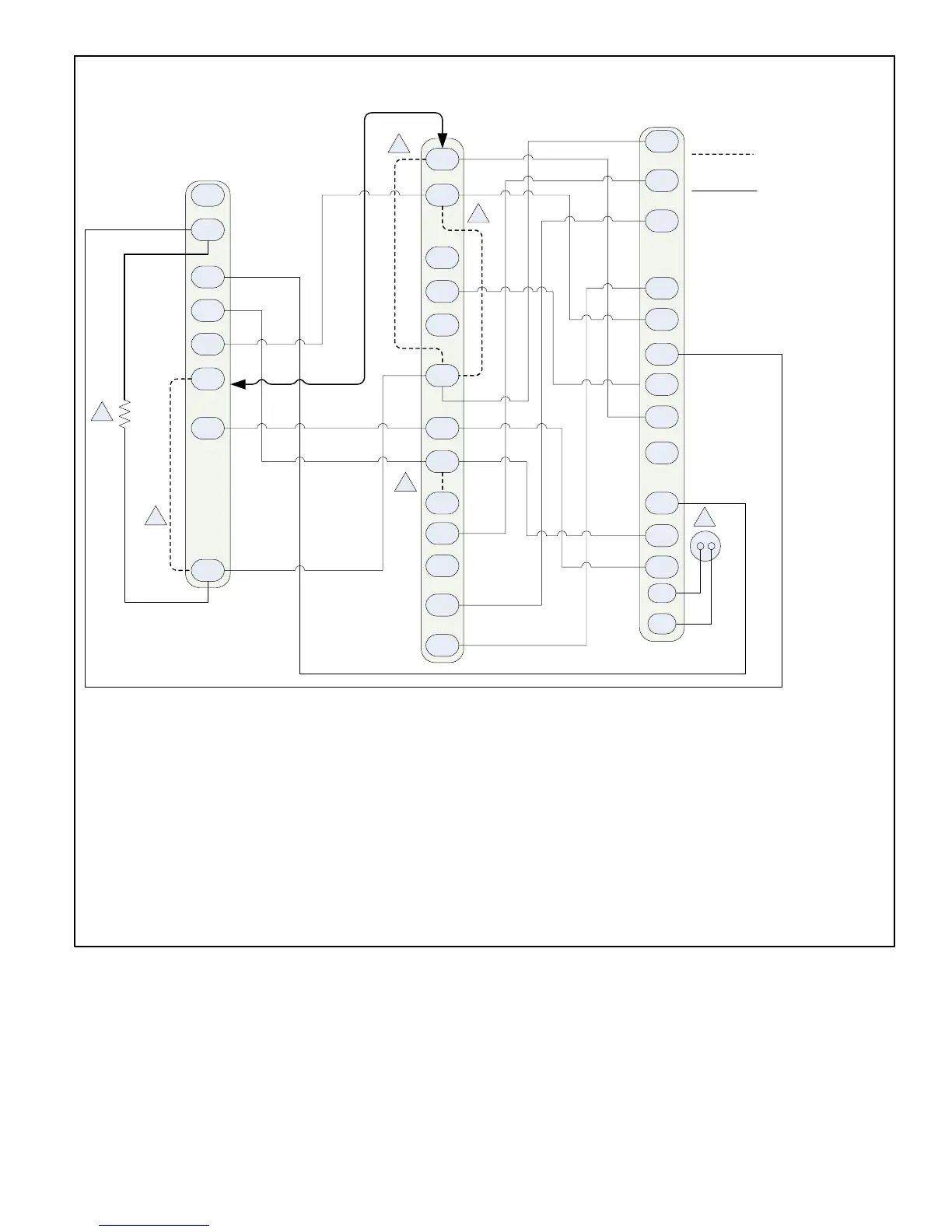
On−board link
Low voltage thermostat
wiring
1. Thermostat T terminals are used for outdoor sensor input. Use for thermostat’s outdoor temperature display (optional).
2. R to L connection is required for this model when using the ComfortSense
®
7000 − catalog number Y0349 only. Resistor Kit (catalog number
47W97) required and ordered separately.
3. Cut on−board link W951 (clippable wire) from R−O HEAT PUMP for heat pump applications.
4. Cut on−board link W915 (clippable wire) for two−stage operation.
5. Cut loop jumper (clippable wire) Short DS to R for Humiditrol
®
applications. This will slow the outdoor unit’s fan speed to a specific RPM. A wire
must be installed between the DS terminals on the furnace and outdoor unit controls. See table 17 for fan speed based on unit capacity.
6. Cut on−board link (clippable wire) DS−R for Humiditrol
®
or Harmony III applications. This will slow the indoor blower motor to the lowest speed
setting. See furnace installation instruction or engineering handbook for lowest fan speed information.
NOTE − For defrost temper with furnace, the optional 67M41 temper kit would be wired between W of from the heat pump control (A175) to the W1
of the furnace control The kit allows for the furnace to cycle on and off during a defrost. It protects the compressor from high refrigeration pressures
during defrost.
Figure 14. ComfortSense® 7000 Series Thermostat Furnace/Two−Stage Heat Pump

 Loading...