Page 76
XP21
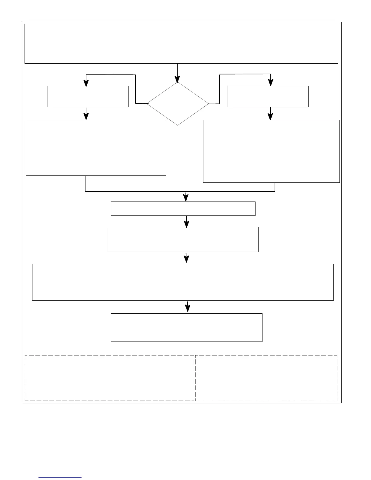
On 24VAC power−up or heat pump control (A175) reset, the heat pump control shall perform the following tasks:
1. Start the anti−short cycle delay.
2. Check temperature sensor and pressure switches at the start of demand.
3. Heat pump control responds to the thermostat input after the anti−short cycle timer expires. If there is no thermostat input, control goes to
standby mode.
Heat Pump control receives
cooling input.
The heat pump control (A175) will apply:
1. 24VAC to compressor contactor output Y1 OUT..
2. 24VAC to reversing valve output O terminal.
3. A field programmed RPM (DC voltage that represents
an RPM output value) is applied to the FAN PWM and
COM terminals.(The control’s 7 segment will display the
field programmed RPM of the outdoor fan motor)
NOTE − If low pressure switch is closed, system will ignore for
90 seconds.
1. For low (S87) and high (S4) pressure switches sequence of
operations, see figures 43 and 44.
2. For temperature switch RT28 sequence of operations, see
figure 45.
3. For Defrost calibration sequence of operations see figure 46.
4. For Defrost sequence of operations see figure 46.
Room thermostat calls for high (two−stage)
The heat pump control will apply::
1. 24VAC to second−stage solenoid output that will energized after the first−stage compressor has been active for a minimum of five (5)
seconds.
2. A field programmed RPM (DC voltage that represents an RPM output value) is applied to the FAN PWM and COM terminals. (The
control’s 7 segment will display the field programmed RPM of the outdoor fan motor)
The outdoor fan motor (B4) receive the (PWM) Pulse Width
Modulation DC volt signal from the control and runs the fan motor
at the field programmed RPM speed.
Two−stage Ambient Lock−in Temperature
Should the ambient temperature be below the selected two−stage lock−in
temperature (jumper in place on jumper pin strip) , the two−stage solenoid
output will be energized, after the 1st stage 5 second delay expires, the
outdoor fan will go to high stage and a Y2 signal will be output to the indoor
unit to cycle the indoor fan to high speed.
Room thermostat
calls for low (one−
stage)
Heat Pump control receives
heating input.
The heat pump control (A175) will apply:
1. 24VAC to compressor contactor output Y1 OUT..
2. A field programmed RPM (DC voltage that represents an
RPM output value) is applied to the FAN PWM and COM
terminals.(The control’s 7 segment will display the field
programmed RPM of the outdoor fan motor)
NOTE − If low pressure switch is closed, system will ignore for 90
seconds.
The outdoor fan motor (B4) receive the (PWM) Pulse Width
Modulation DC volt signal from the control and runs the fan motor
at the field programmed RPM speed.
Figure 42. One− and Two−Stage Cooling Sequence of Operations (103369−01 Only)

 Loading...