Page 25
I-UNIT COMPONENTS
blue.
ELECTROSTATIC DISCHARGE (ESD)
Precautions and Procedures
CAUTION
electronic components. Take precautions
to neutralize electrostatic charge by
touching your hand and tools to metal
prior to handling the control.
A-Control Box Components
control box is in the outdoor section to the left of the blow-
er and heat section.
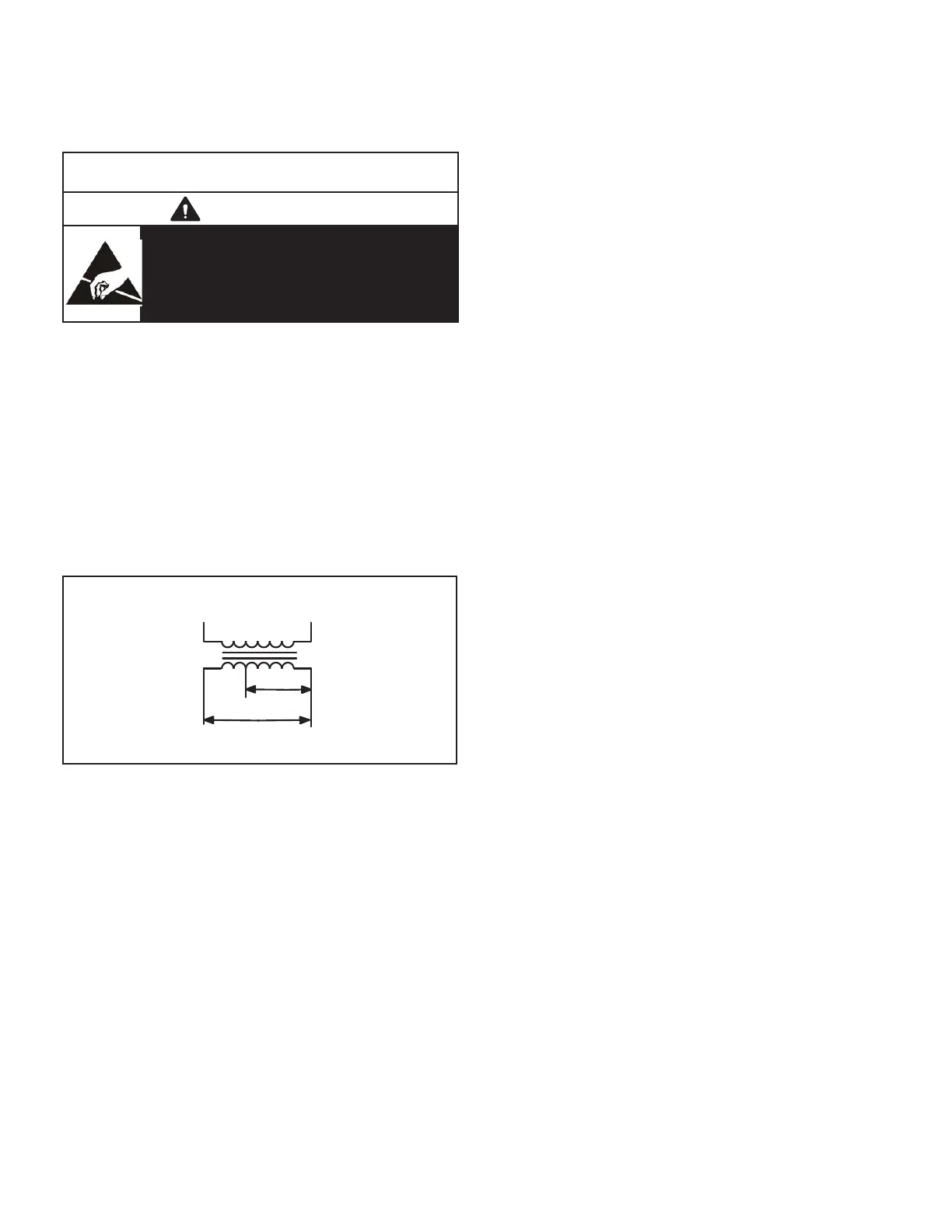
1-Control Transformer T1
in the control box. Transformer supplies powerto control
-
age transformers use two primary voltage taps as shown
use asingle primary voltagetap.
BLUE YELLOW
ORANGE
RED
BLACK
230 VOLTS
208 VOLTS
PRIMARY
SECONDARY
208/230V TRANSFORMER
FIGURE 3
2-C. A. I. Transformers T3 (G, J voltage)
mounted in the control box. The transformers have an out-
-
3-Fan Capacitor C1 (three phase)
Fan capacitors C1 is used to assist in the start up of con-
-
door fan motor nameplate.
4-Dual Capacitor C12 (single phase)
A single dual capacitor is used for both the outdoor fan
capacitor for ratings
5-Compressor Contactor K1
-
sponse to thermostat demand. Three phase units use two
phase units use single pole double break contactors with
6-Blower Contactor K3
-
energizes the indoor blower motor B3 in response to blow-
er demand.
7-Condenser Fan Relay K10 (G, J voltage)
8-Crankcase Heater Delay DL48 & Crankcase Heater
Relay K191
-
ergized during and immediately following compressor
compressor is energized.
9-Gas Relay K72 (two-stage units)
10-Relay K239 (-074 Units)
-
ergize the blower on high speed.
11-Relay K250 (-074 Units)
-
the signal to K37 energizing the blower on high speed and
speed.
12-Blower Contactor K37 (-074 Units)
On two-speed operation K37 acts as the high speed blow-
er contactor and K3 acts as the low speed contactor in
response to blower demand.
13-Blower Delay DL3 &DL50 (-074 Units)
delay switching from high speed to low speed.
 Loading...