Page 35
IMPORTANT
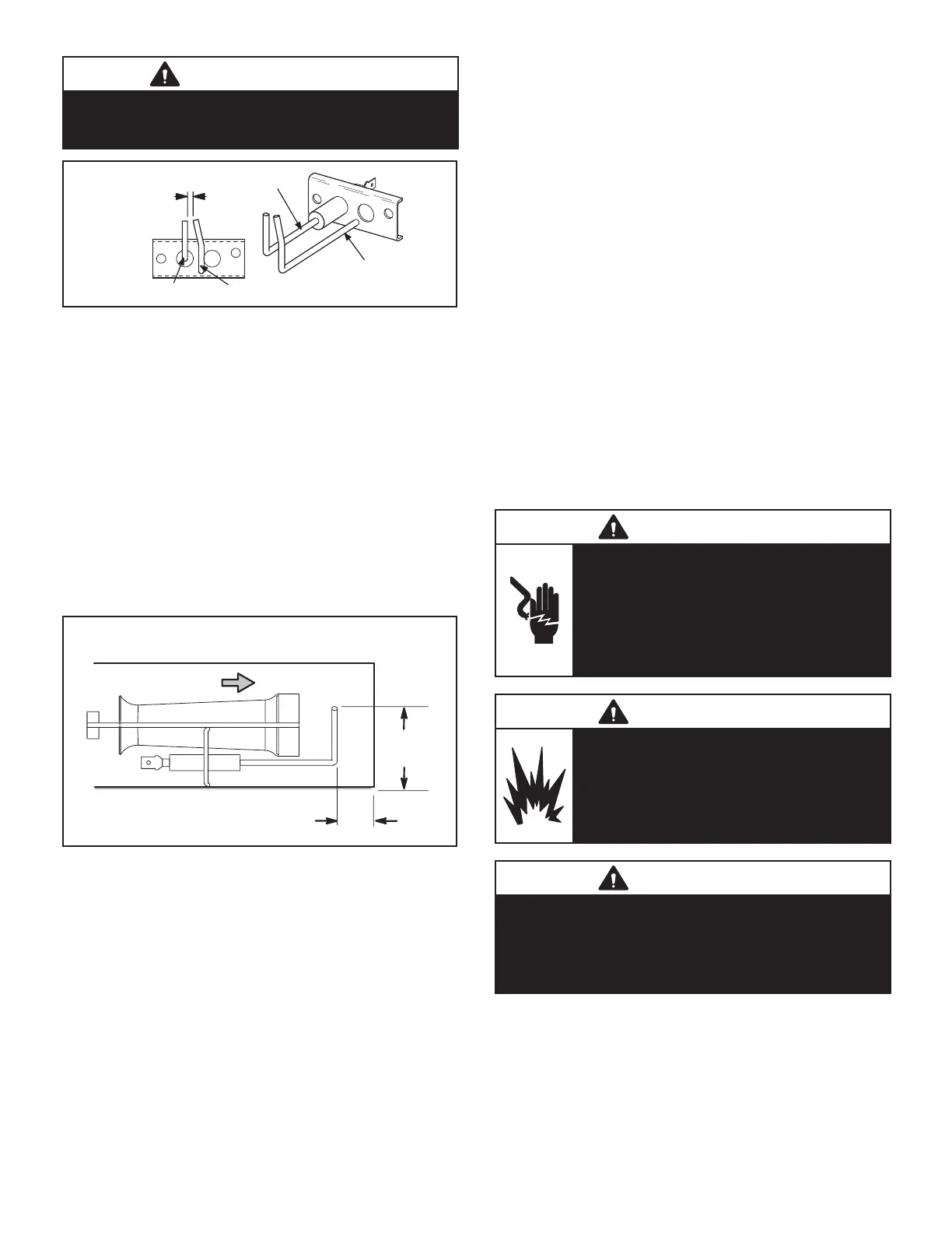
n order to maximize spark energy to electrode, high
voltage wire should touch unit cabinet as little as
possible
GROUND
ELECTRODE
ELECTRODE
(3.2 mm ± .4 mm)
FIGURE 12
10-Flame Sensor Figure 13
-
thest to the left. The sensor is mounted through a hole
envelope of the left most burner. The sensor assembly is
fastened to burner supports and can be removed for ser-
vice without removing any part of the burners.
-
mediately or after the eight-second trial for ignition. During
-
SIDE VIEW SENSOR
1-3/4”
(45mm)
3/8”
(10mm)
Gas Flow
FIGURE 13
II-PLACEMENT AND INSTALLATION
Make sure the unit is installed in accordance with the in-
stallation instructions and all applicable codes. See ac-
cessories section for conditions requiring use of the op-
III-START UP - OPERATION
A-Preliminary and Seasonal Checks
1- Make sure the unit is installed in accordance with the
installation instructions and applicable codes.
-
to unit diagram located on inside of control panel.
3- Check to ensure that refrigerant lines are in good con-
dition and do not rub against the cabinet or other refriger-
ant lines.
the power company and have the voltage corrected be-
fore starting the unit.
voltage is not within range listed on unit nameplate stop
for maximum rated load amps.
B-Heating Start up
FOR YOUR SAFETY READ BEFORE LIGHTING
WARNING
Electric shock hazard. Can cause injury
or death. Do not use this unit if any part
has been under water. Immediately call a
unit and to replace any part of the control
system and any gas control which has
been under water
WARNING
Danger of explosion. Can cause injury
or product or property damage. If
overheating occurs or if gas supply
electrical supply.
WARNING
SMOKE POTENTIAL
The heat exchanger in this unit could be a source
respect to building occupants and property. Vent
initial supply air outside when possible.
 Loading...