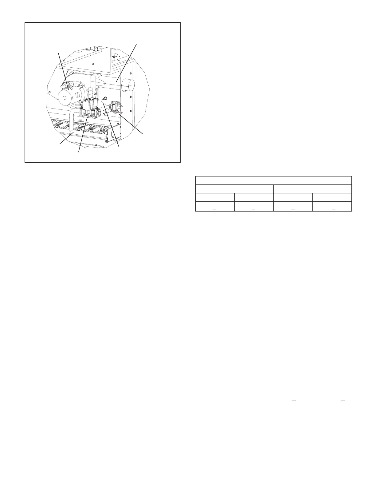
EasyManuals Logo

Lennox ZGB Series User Manual

Lennox ZGB Series
55 pages
To Next Page IconTo Next Page
To Previous Page IconTo Previous Page
Page #34 background imageLoading...
Page #34 background image

BURNER BOX ASSEMBLY
S18
Combustion Air
Prove Switch
Gas Valve
Gas
Manifold
Vent Connector
B6
Combustion
Air Inducer
Combustion Air
Prove Switch Tubing
FIGURE 11
6-Combustion Air Inducer B6
Combustion air inducers provide air to the corresponding
burners while clearing the combustion chamber of ex-
haust gases. The inducer begins operating immediately
upon receiving a thermostat demand and is de-energized

       
     
       
protection. Inducers are supplied by various manufactur-

electrical ratings can be found on the unit rating plate.
         -
        
the combustion air inducer to vent exhaust gases from

-
        

the combustion air prove switch is closed and the delay is

-
       
sensed or at the end of the eight second trial for ignition.
        -
       
start the inducer in high speed for second-stage heat


All combustion air inducer motors are sealed and cannot
be oiled. The inducer cannot be adjusted but can be re-
moved from the vestibule to clean the wheel.
7-Combustion Air Motor Capacitor C3
The combustion air inducer motors in all ZGB units require
run capacitors. Capacitor C3 is connected to combustion
-
bustion air motor nameplate.
8-Gas Valves GV1
Units are equipped with a single or two stage gas valve.
-
gized by the ignition control simultaneously with the spark

second stage operator is energized directly from A3. A
󰀨
󰀨󰀨

󰀨


shows factory gas valve regulation pressures.
TABLE 7

Natural 
 High  High
1.7  3.5    
9-Spark Electrode (Ignitor) Figure 12
An electrode assembly is used for ignition spark. The elec-
trode is mounted through holes under the burner located
farthest to the right. The electrode tip protrudes into the
-
sembly is fastened to burner supports and can be removed
for service without removing any part of the burners.


burner to burner until all are lit.
The spark electrode is connected to the ignition control by

female quick connects on both ends of the wire.
NOTE - If electrode wire must be replaced, wire and sup-
pression must be same type cable. See www.davenet for
replacement.
The spark electrode assembly can be removed for inspec-
tion by removing the screw securing the electrode assem-
bly and sliding it out of unit.

and gapped correctly. Spark gap may be checked with
appropriately sized twist drills or feeler gauges. Discon-
nect power to the unit and remove electrode assembly.



Questions and Answers:

Question and Answer IconNeed help?

Do you have a question about the Lennox ZGB Series and is the answer not in the manual?

Lennox ZGB Series Specifications

General IconGeneral
BrandLennox
ModelZGB Series
CategoryAir Conditioner
LanguageEnglish

Related product manuals