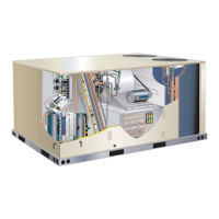
SPARK GAP
SHOULD BE 1/8”
(3mm)
FIGURE 19
WARNING
Danger of explosion. Can cause injury
or death. Do not overtighten main burner
mounting screws. Snug tighten only
7 -
lighting instructions attached to unit and use
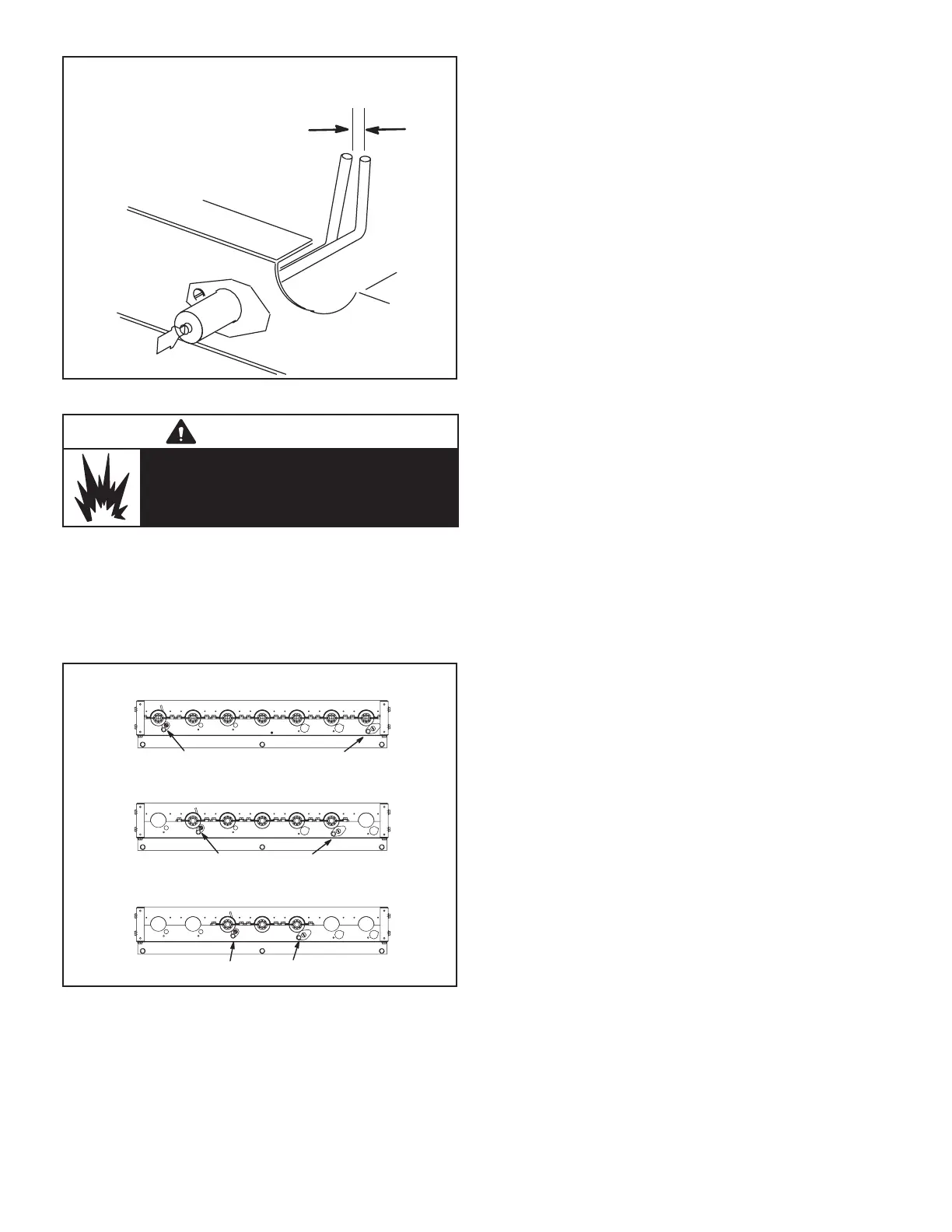
150,000 BTUH - 7 BURNERS
108,000 BTUH - 5 BURNERS
65,000 BTUH - 3 BURNERS
SENSOR IGNITOR
SENSOR IGNITOR
SENSOR IGNITOR
FIGURE 20
D-Combustion Air Inducer
A combustion air proving switch checks combustion air in-
ducer operation before allowing power to the gas control-
ler. Gas controller will not operate if inducer is obstructed.
inducer wheel should be checked and cleaned prior to
-
riodically during the heating season to establish an ideal
cleaning schedule.
1 -
2 -
of the outdoor section under the control box.
3 -
Clean inducer wheel blades with a small brush and
damage exposed fan blades. Clean accumulated
5 -
connector to original location and secure with
retained screws. It is recommended that gaskets be
replaced during reassembly.
7 - Clean combustion air inlet louvers on heat access
panel using a small brush.
E-Flue Passageway and Flue Box
-
-
tightly sealed.
F-Evaporator Coil
Inspect and clean coil at beginning of each cooling season.
Clean using mild detergent or commercial coil cleanser.
Flush coil and condensate drain with water taking care not
G-Condenser Coil
Clean condenser coil annually with water and inspect
monthly during the cooling season.
Note - Do not use commercial coil cleaner on the all alu-
minum coil. Using anything other than water could result
in corrosion and/or leaks.
Clean the all-aluminum coil by spraying the coil steadily
from the coil face. Take care not to fracture the braze be-
work cautiously to prevent damage.
H-Supply Blower Wheel
Annually inspect supply air blower wheel for accumulated
access panel or to clean blower wheel.
 Loading...