A
B
C
D
Open
Min
Pos
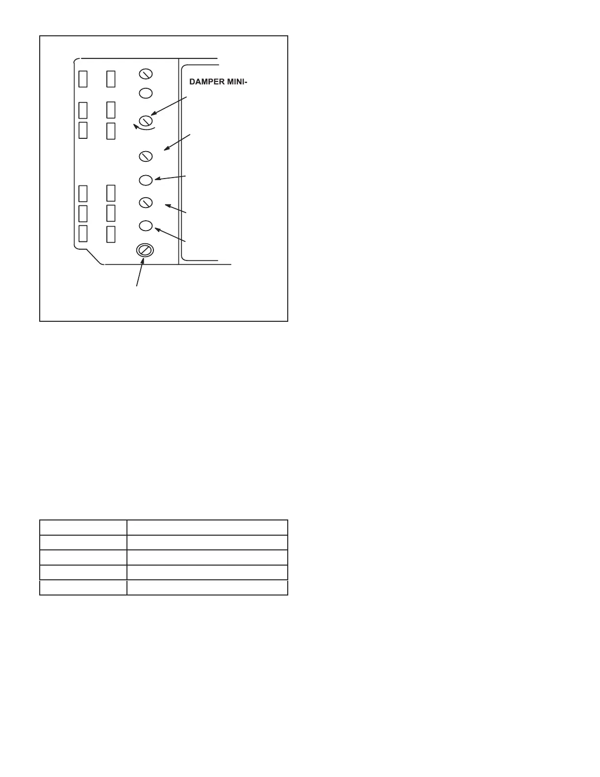
FREE COOLING SETPOINT;
A=Completely counterclockwise
D=Completely clockwise
OUTDOOR AIR
SUITABLE LED
Free
Cool
DCV
EXH
EXH
Set
2V 10V
DCV
Max
2V 10V
DCV
Set
2V 10V
IAQ SETPOINT
IAQ READING IS
ABOVE SETPOINT
MUM POSITION
IAQ MAXIMUM
POSITION
(set higher than
minimum position)
FIGURE 27
Free Cooling Setpoint
Outdoor air is considered suitable when temperature and
humidity are less than the free cooling setpoints shown
TABLE 13
ENTHALPY CONTROL SETPOINTS
Control Setting
A
B
C
D
Damper Minimum Position
1 - Set thermostat to occupied mode if the feature is
OC are connected if using a thermostat which does
not have the feature.
2 -
desired fresh air percentage.
Note - Damper minimum position can be set lower
than traditional minimum air requirements when
an IAQ sensor is specied. Dampers will open to
DCV MAX setting (if CO2 is above setpoint) to meet
traditional ventilation requirements.
3 - Measure outdoor air temperature. Mark the point
Measure return air temperature. Mark that point on
5 -
temperature. Mark that point on the top line of chart
Draw a straight line between points A and B.
7 - Draw a vertical line through point C.
Draw a horizontal line where the two lines meet.
MIN POS SET potentiometer higher. If fresh air
until calculation reads desired fresh air percentage.
DCV Set and Max Settings
Adjust settings when an optional IAQ sensor is installed.
The DCV SET potentiometer is factory-set at approxi-
DCV SET potentiometer to the approximate setting speci-
The DCV MAX potentiometer is factory-set at approxi-
-
ers will open approximately half way when CO2 rises
above setpoint. Adjust the DCV MAX potentiometer to the
Note - DCV Max must be set higher than economizer min-
imum position setting for proper demand control ventila-
tion.
 Loading...