G-Power Exhaust Fans (Field-Installed)
-
-
vide exhaust air pressure relief and also run when return
air dampers are closed and supply air blowers are oper-
more detail.
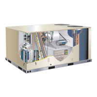
R EXHAUST FAN - DOWNFLOW APPLICATIONS
POWER EXHAUST FAN
FIGURE 30
H-Control Systems
ZGB series units. All thermostat wiring is connected to low
voltage pigtails located in the control box. Each thermo-
stat has additional control options available. See thermo-
stat installation instructions for more detail.
-
chanical thermostat is a two stage heat / two stage cool
thermostat with dual temperature levers. A non-switch-
ing or manual system switch subbase may be used.
heat / two stage cool electronic thermostat may be
used.
I-Indoor Air Quality (CO2) Sensor A63
The indoor air quality sensor monitors CO2 levels and
to the CO2 levels. The sensor is mounted next to the in-
-
door air quality sensor installation instructions for proper
adjustment.
J-LP / Propane Kit (Field-Installed)
-
lation instructions
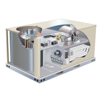
25” MIN.
20”
2 1/2”
16 1/2”
16 1/2”
POWER EXHAUST FAN - HORIZONTAL APPLICATIONS
FIELD-PROVIDED
AND INSTALLED
DUCTWORK
POWER EXHAUST FAN
FIGURE 31
 Loading...