Do you have a question about the Lenovo E24-28 and is the answer not in the manual?
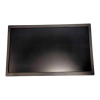
Prepare soft cloth and sponge for horizontal placement.
Hold LCD by the side, avoid touching or pressing the panel directly.
Phillips screwdriver required for disassembly and re-assembly.
Spacer screwdriver for specific disassembly tasks.
C/D disassembly tool for releasing hooks.
Protective gloves or soft cloth for handling.
Place monitor on a flat surface with EPE protection underneath.
Remove 4 screws securing the stand using a screwdriver.
Detach the monitor stand from the main unit.
Use disassembly tool to release rear cover hooks.
Disassemble back cover, disconnect speaker cable.
Unscrew the middle frame using a screwdriver.
Detach the keyboard component from its mounting.
Remove light cables and FFC cable.
Take out the isolation cover.
Detach any acetate tape securing components.
Detach the black Mylar sheet from the power board.
Unscrew all screws to remove the PCB.
Take out the PCB and peel off all Mylar.
Detach thermal pads from the power PCB.
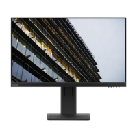
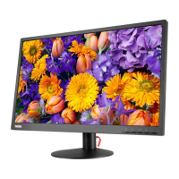
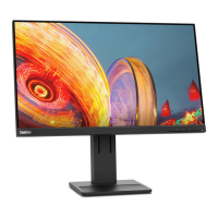
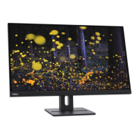
| Screen Size | 23.8 inches |
|---|---|
| Panel Type | IPS |
| Refresh Rate | 60 Hz |
| Aspect Ratio | 16:9 |
| Brightness | 250 cd/m² |
| Contrast Ratio | 1000:1 |
| Audio Out | Yes |
| Viewing Angle | 178° (H) / 178° (V) |
| Built-in Speakers | No |
| VESA Mount | 100 x 100 mm |
| Color Gamut | 72% NTSC |
| Weight | 3.5 kg (with stand) |
| Resolution | 1920 x 1080 |
| Response Time | 4 ms |
| Ports | HDMI, VGA, DisplayPort |
| Stand | Tilt |
| Power Consumption | 18 W (typical) |