Replacement procedure
1. Remove the computer stand. See “Computer stand” on page 61.
2. Remove the rear cover. See “Rear cover” on page 65.
3. Remove the optical drive. See “Optical drive” on page 66.
4. Remove the optical drive holder. See “Optical drive holder” on page 69.
5. Remove the system board shield. See “System board shield” on page 71.
6. Remove the VESA mount bracket cover. See “VESA mount bracket cover” on page 74.
7. Remove the VESA mount bracket. See “VESA mount bracket” on page 76.
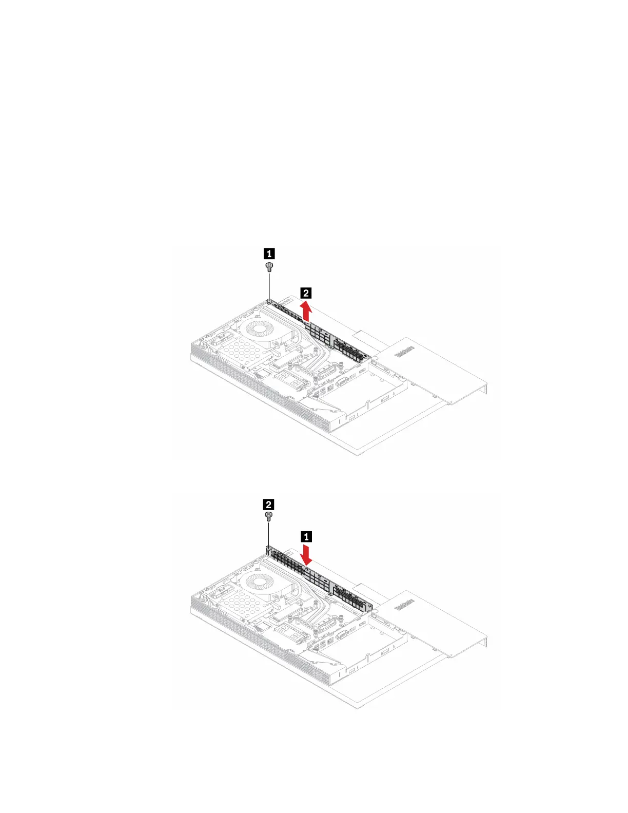
8. Depending on your computer model, refer to one of the following to replace the bump cover.
• M70a
Figure 61. Removing the bump cover
Figure 62. Installing the bump cover
Chapter 6. Hardware removal and installation 89