Hazardousvoltage,current,andenergylevelsarepresentinsideanycomponentthathasthislabel
attached.Therearenoserviceablepartsinsidethesecomponents.Ifyoususpectaproblemwith
oneoftheseparts,contactaservicetechnician.
Toreplacethepowersupplyassembly,dothefollowing:
1.Removeallmediafromthedrivesandturnoffallattacheddevicesandthecomputer.Then,disconnect
allpowercordsfromelectricaloutletsanddisconnectallcablesthatareconnectedtothecomputer.
2.Removethecomputercover.See“Removingthecomputercover”onpage90.
3.Disconnectthepowersupplyassemblycablesfromalldrivesandfromthe24-pinpowerconnectorand
4-pinpowerconnectoronthesystemboard.See“Locatingpartsonthesystemboard”onpage73.
4.Releasethepowersupplyassemblycablesfromthecableclipsandtiesinthechassis.
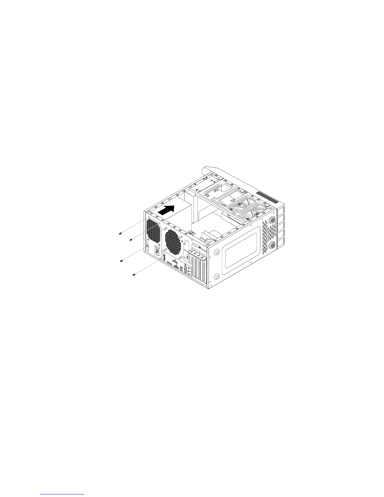
5.Laythecomputeronitssideandremovethefourscrewsattherearofthechassisthatsecurethe
powersupplyassembly.
Figure34.Removingthescrewsforthepowersupplyassembly
6.Slidethepowersupplyassemblytothefrontofthecomputer,andthenliftitoutofthechassis.
7.Ensurethatthenewpowersupplyassemblyisthecorrectreplacement.Somepowersupplyassemblies
automaticallysensethevoltage,somepowersupplyassembliesarevoltagespecific,andsome
powersupplyassemblieshaveavoltage-selectionswitch.Ifyourpowersupplyassemblyhasa
voltage-selectionswitch,makesurethatyousetthevoltage-selectionswitchtomatchthevoltage
availableatyourelectricaloutlet.Ifnecessary,useaballpointpentoslidethevoltage-selectionswitch
tothecorrectposition.
•Ifthevoltagesupplyrangeinyourlocalcountryorregionis100–127Vac,setthevoltage-selection
switchto115V.
•Ifthevoltagesupplyrangeinyourlocalcountryorregionis200–240Vac,setthevoltage-selection
switchto230V.
8.Installthenewpowersupplyassemblyintothechassissothatthescrewholesinthepowersupply
assemblyalignwiththoseinthechassis.
9.Installandtightenthefourscrewstosecurethepowersupplyassembly.
Note:UseonlyscrewsprovidedbyLenovo.
10.Reconnectthepowersupplyassemblycablestothesystemboardandeachofthedrives.
Chapter9.ReplacingFRUs(machinetypes:10B0,10B1,10B2,10B3,10HJ,and10HK)105
 Loading...