Do you have a question about the Lenovo ThinkPad P14s Gen 4 and is the answer not in the manual?
Follow rules to ensure general safety when working with machines.
Observe rules when working on electrical equipment.
Checklist to identify potentially unsafe conditions before servicing.
Procedures to protect against electrostatic discharge damage.
Electrical grounding is required for operator safety and system function.
Safety notices provided in multiple languages.
Guidelines and strategy for replacing Field Replaceable Units.
Procedures for replacing SSDs, including data backup.
Using error codes and symptoms to diagnose failures.
Information on CTO, special-bid, and standard models for FRU replacement.
Introduces different model types and how to identify them.
Instructions on how to find FRU information for a product.
Information to include in parts exchange/return forms.
Procedures for identifying and correcting computer problems.
Steps to solve computer problems using documentation and diagnostic tools.
Running quick tests to troubleshoot problems.
Using the preinstalled UEFI diagnostic program for hardware testing.
Creating and using bootable media for diagnostics.
Procedures to verify battery or AC power adapter functionality.
Steps to check the functionality of the AC power adapter.
How to check battery status and charging.
Procedure to check the coin-cell battery voltage.
Information on resetting or restoring the Windows operating system.
Information on setting and managing BIOS passwords for security.
Protects system from unauthorized startup.
Secures data on the storage drive.
Protects system information in UEFI BIOS.
Controls security features via UEFI BIOS or WMI.
Information on sleep and hibernation modes.
Computer enters low power state, screen goes blank.
System state saved to storage; system is powered off.
Lists symptoms and errors with possible causes and FRU actions.
Table of error codes and corresponding FRU actions.
Common error messages and their solutions.
Decoding beep errors using smartphone app.
Troubleshooting symptoms without audible beeps.
Diagnosing issues related to the LCD panel.
Analyzing and resolving problems that occur sporadically.
Procedures for issues not identified by diagnostics.
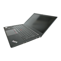
Identifies physical controls and connectors on the computer.
Locations of front-panel components like camera and microphone.
Ports and connectors on the sides of the computer.
Location of the nano-SIM card tray.
Location of the emergency-reset hole.
Identifying Field Replaceable Units and Customer Replaceable Units.
Lists major replaceable parts with self-service/optional service classification.
Lists replaceable parts for the LCD assembly.
Lists screws, kits, and labels.
Identifies system board connectors and their associated cables.
List of essential tools required for servicing the computer.
Guidelines for tightening screws, especially nylon-coated ones.
Instructions for restoring system unit serial numbers and UUIDs.
Procedure to restore serial number after system board replacement.
Procedure to create a new UUID for the system board.
Using utilities to manage Engineering Change Announcement data.
General rules and precautions before servicing.
Important steps before starting any FRU replacement.
Steps to safely disable the internal battery before service.
Procedure to remove the nano-SIM card and tray.
Removal and installation procedure for the keyboard.
Removal and installation procedure for the base cover.
Procedure for removing and replacing the internal battery.
Procedure for replacing M.2 SSD and bracket for Intel models.
Procedure for replacing M.2 SSD and bracket for AMD models.
Procedure for replacing the wireless WAN card.
Procedure for removing and replacing the I/O bracket.
Procedure for removing and replacing the thermal fan assembly.
Procedure for replacing USB board components.
Procedure for removing and replacing the speaker assembly.
Procedure for removing and replacing the coin-cell battery.
Procedure for replacing the memory module on Intel models.
Procedure for replacing RFID reader and cable.
Procedure for removing and replacing the trackpad and its cable.
Procedure for replacing the NFC module and its cable.
Procedure for replacing smart card reader components.
Procedure for replacing power button board and cable.
Procedure for replacing the wireless WAN antenna assembly.
Important notices and procedure for replacing the system board.
Procedure for removing and replacing the LCD unit.
Procedure for replacing the LCD bezel sheet and bezel.
Procedure for removing and replacing the LCD hinges.
Procedure for replacing LCD panel and adhesive tapes.
Procedure for removing and replacing the LCD cable.
Procedure for replacing camera and microphone module.
Procedure for removing and replacing the LCD cover assembly.
| Storage | Up to 2TB PCIe SSD |
|---|---|
| Dimensions | 329 x 227 x 17.9 mm (12.95 x 8.94 x 0.70 inches) |
| Graphics | Intel Iris Xe |
| Operating System | Windows 11 Pro |
| Battery | 52.5Wh |
| Weight | 1.4 kg (3.09 lbs) |
| Ports | 2 x USB-C, 2 x USB 3.2, HDMI, MicroSD card reader, Audio jack |
| Wireless | Wi-Fi 6E, Bluetooth |
| Webcam | 1080p with privacy shutter |
| Audio | Stereo speakers |
| Security | Fingerprint reader, TPM 2.0 |