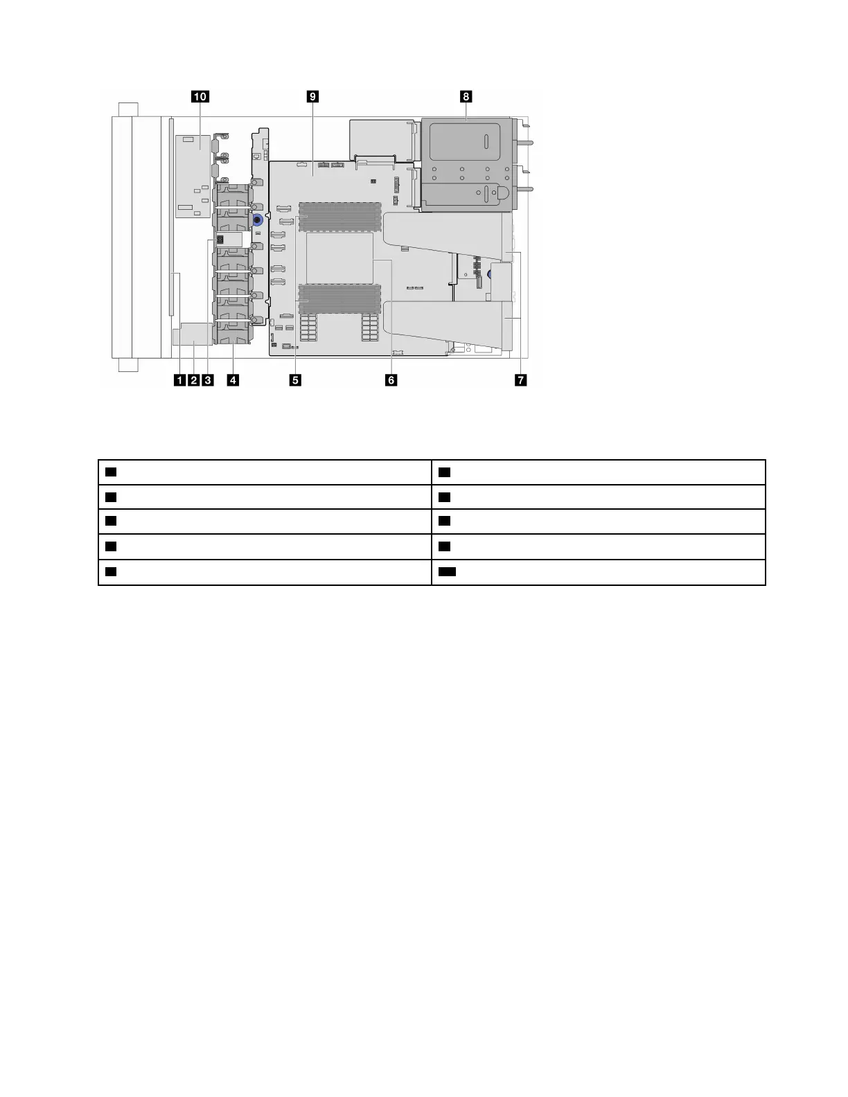
Figure 8. Server top view for standard configurations
Table 18. Component identification (Top view)
1 Front backplane
2 RAID flash power module
3 Intrusion switch 4 Fan modules
5 Memory modules 6 Processor and heat sink
7 Riser assemblies
note 1
8 Power supply units
9 System board (system board assembly) 10 Internal CFF HBA/RAID module
Notes:
1. The illustration shows the server rear configuration with 2 riser assemblies. The server rear
configurations vary by server model. For details, see
“Rear view” on page 23.
Top view for the liquid cooling configuration
The following top view is based on liquid cooling configuration.
Chapter 2. Server components 29

 Loading...


