20 SF01U
11.0 SCF CONTROL WIRING DIAGRAMS
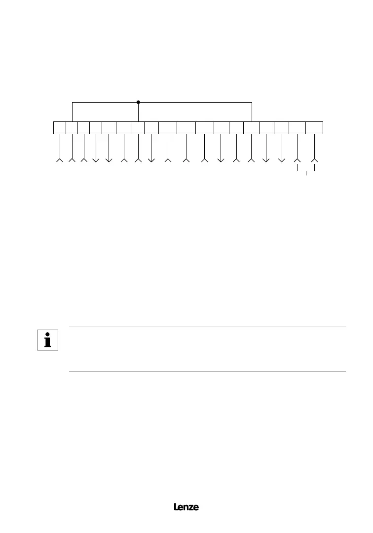
11.1 SCF TERMINAL STRIP
Shown below is the terminal strip on the main control board, along with a brief description of
the function of each terminal.
1 2
5 6
12
TXA TXB
2 13A 13B 13C14 15 2
STOP
CIRCUIT COMMON
0-10 VDC SPEED REFERENCE INPUT
10 VDC SUPPLY FOR SPEED POT
0-10 OR 2-10 VDC OUTPUT: FREQ. OR LOAD
0-10 OR 2-10 VDC OUTPUT: LOAD
CIRCUIT COMMON
START
TB-13A FUNCTION SELECT
TB-13B FUNCTION SELECT
TB-13C FUNCTION SELECT
OPEN-COLLECTOR OUTPUT
OPEN-COLLECTOR OUTPUT
RS-485 SERIAL
COMMUNICATIONS
CIRCUIT COMMON
4-20 mA SPEED REFERENCE INPUT
11 25 31
30
12 VDC SUPPLY (50 mA MAX)
The TB-2 terminals are internally connected to each other
NOTE
The function of terminals TB-13A, TB-13B, TB-13C, TB-14, TB-15, TB-30,
and TB-31 are dependent on the programming of certain parameters. Refer
to Section 15.0 - DESCRIPTION OF PARAMETERS.
Additional information on operating the drive from the terminal strip can be found in Section
10.0. The following diagrams provide a quick reference to wire the drive for the most common
configurations.
Artisan Technology Group - Quality Instrumentation ... Guaranteed | (888) 88-SOURCE | www.artisantg.com