EasyManua.ls Logo

Lenze EPL 10200-EI - User Manual

Lenze EPL 10200-EI
78 pages
Go to English
Print Icon
To Next Page IconTo Next Page
Loading...
Drive PLC
EDK10200EV3
!Qzö
L
Montageanleitung
Mounting Instructions
Instructions de montage
!Qzö
Show/Hide Bookmarks

Questions and Answers

  • K
    Kathy LeeAug 17, 2025
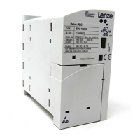
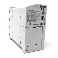
    What to do if I have BUS-OFF error (many communication errors occurred) on Lenze DC Drives?
    • N
      Nicole DonovanAug 17, 2025
      If you're getting a BUS-OFF error on your Lenze DC Drives, it means the Drive PLC has received too many incorrect telegrams via the system bus and has been disconnected. Check whether a bus terminator is available, shield the control cables, check the PE connection, and if necessary, reduce the baud rate to address this issue.
  • C
    Corey Chapman MDAug 19, 2025
    What causes system error in Lenze EPL 10200-EI DC Drives?
    • E
      Eric ColeAug 20, 2025
      A system error in Lenze DC Drives can be caused by strong interference on control cables, in which case you should shield the control cables. Another potential cause is ground or earth loops in the wiring.
  • J
    Jose WilsonAug 22, 2025
    What causes external fault (TRIP-Set) in Lenze EPL 10200-EI DC Drives?
    • P
      Pamela WebbAug 22, 2025
      An external fault (TRIP-Set) in Lenze DC Drives occurs when a digital signal assigned to TRIP set has been activated. To solve this, check the external encoder.
  • M
    Michele GillAug 26, 2025
    What causes communication error to AIF in Lenze EPL 10200-EI?
    • D
      dodsonmichelleAug 26, 2025
      A communication error to AIF in Lenze DC Drives is caused by faulty transmission of control commands via AIF. To resolve this, insert the communication module into the hand terminal.
  • F
    Frederick GreenAug 28, 2025
    What causes communication error to CAN-IN2 on Lenze EPL 10200-EI DC Drives?
    • S
      sharonwhiteAug 28, 2025
      A communication error to CAN-IN2 on Lenze DC Drives occurs when the CAN-IN2-object receives faulty data or communication is interrupted. Ensure plug-in connection - bus module, check FIF, check transmitter, and increase monitoring time under C0357/2 if necessary.
  • R
    Russell BowersAug 30, 2025
    What causes communication error to CAN-IN1 with event or time control on Lenze DC Drives?
    • T
      Thomas SmithAug 30, 2025
      A communication error to CAN-IN1 with event or time control on Lenze DC Drives happens when the CAN-IN1-object receives faulty data or communication is interrupted. Ensure plug-in connection - bus module, check FIF, check transmitter, and increase monitoring time under C0357/3 if necessary.
  • J
    jessica55Sep 2, 2025
    What to do if my Lenze DC Drives PC does not respond?
    • S
      Samantha TuckerSep 2, 2025
      If your PC isn't responding when using Lenze DC Drives, it might be because the system-bus module was disconnected from the parallel port (LPT) of the PC during operation; try restarting the PC. Another cause could be that a print job was sent to the interface/port used by the system-bus module. If this is the case, restart the PC and use the other parallel port (LPT) for printing.
  • K
    Kathy HoffmanSep 5, 2025
    What to do if there is no control signal on the digital outputs (X2) of Lenze EPL 10200-EI?
    • R
      Ryan CunninghamSep 5, 2025
      If there's no control signal on the digital outputs (X2) of your Lenze DC Drives, it could be due to a missing connection between X1/+24 and X1/O24. Set up the connection.
  • C
    Crystal NixonSep 7, 2025
    What causes faulty transfer of PAR1 with keypad/PC in Lenze DC Drives?
    • C
      Chad LesterSep 8, 2025
      Faulty transfer of PAR1 with keypad/PC in Lenze DC Drives is due to a defective PAR1. To resolve this, repeat the data transfer or load the Lenze setting.
  • M
    morsetheodoreSep 12, 2025
    What causes initialisation error during transfer of parameter set in Lenze EPL 10200-EI?
    • S
      Samantha HoltSep 12, 2025
      An initialisation error during the transfer of the parameter set in Lenze DC Drives is caused by a fault detected during the transfer of the parameter set to the Drive PLC, or the parameter set does not match the Drive PLC. Correct the parameter set to solve this.

Summary

Safety Information

People Responsible for Safety

Defines operator and qualified personnel roles for system safety.

Application as Directed

Specifies industrial use and compliance with directives for Drive PLCs.

Installation Safety Precautions

Covers unit installation regulations, protection from loads, and handling sensitive components.

Electrical Connection and Operation Safety

Details voltage limits, prohibited connections, and safe operation rules.

Maintenance and Service Guidelines

Emphasizes adherence to manufacturer's documentation and keeping safety instructions.

Items Supplied

Overview of Supplied Components

Lists all items included in the package, such as terminal strips, clamps, and the PLC.

Technical Data

General Data and Application Conditions

Covers conformity, approvals, supply conditions, and climatic requirements.

DC Supply Voltage Specifications

Details voltage range, current limits, and external supply for outputs.

Temperature, Power Derating, and Environment

Specifies temperatures, derating, vibration resistance, and enclosure rating.

PLC Functionality: Inputs and Outputs

Describes digital/analog input/output types, data, and cycle times.

Dimensions for Standard Fixing

Physical Dimensions and Mounting Details

Provides specific measurements (a, b, c, etc.) for physical installation.

Installation According to EMC

Mounting Plate and Surface Requirements

Specifies the need for an electrically conductive mounting surface.

Cable Screen Grounding and Shielding

Details grounding methods for HF screen connections via PE.

Analog and System Bus Cable Requirements

Mandates screened cables and bus termination for analog and CAN signals.

Terminal Strip Wiring

Safety Precautions for Wiring

Provides critical safety warnings like wiring before plugging and power disconnection.

Wiring Procedure Steps

Illustrates the basic steps for connecting wires to terminal strips.

Terminal Strips Overview

Device Terminal Layout (Top View)

Shows the arrangement of terminal strips X1, X2, X3, X5 on the top of the unit.

Device Terminal Layout (Bottom View)

Depicts terminal strips X4 and X5 on the bottom of the unit.

Control Connections

Top Terminal Connections and Voltage Warning

Illustrates connections on the top and warns about supply voltage limits.

Connection Elements Overview

Identifies required and possible connection types like encoder, load, emergency off.

Terminal Details: Supply, Digital, Analog, CAN

Provides comprehensive details for all terminal types: voltage, digital, analog, and CAN.

Analog Signal Adjustment Tip

Suggests using function blocks for analog signal adjustment.

System Bus (CAN) Wiring

System Cable Specifications

Details cable types, lengths, resistance, and capacitance for CAN bus.

Bus Terminating Resistors

Explains the placement and use of 120 Ω terminating resistors on the bus.

CAN Bus Features

Lists features like protocol, baud rates, reliability, and bus device limits.

Function Module Mounting

Preparation and Module Installation

Covers removing protective covers and plugging in the function module.

Function Module Wiring Reference

Directs users to specific mounting instructions for function module wiring.

Function Module Software Notes

Explains automatic detection of missing or incompatible function modules based on software version.

Communication Module Mounting

Automation Interface (AIF) and Modules

Explains the AIF's role and lists compatible keypad and fieldbus modules.

Fieldbus Module Types

Lists various fieldbus modules like LECOM, INTERBUS, PROFIBUS, DeviceNet, CANopen.

Fieldbus Module Wiring Tip

Advises referring to specific installation instructions for fieldbus module wiring.

Extension Board Mounting

Preparation and Board Installation

Details removing covers, attaching pin connectors, and inserting the extension board.

Extension Board Wiring Reference

Refers to specific mounting instructions for extension board wiring.

Software Version Notes on Detection

Explains how Drive PLC detects extension board issues based on software version.

Function Blocks for Board Management

Describes using function blocks to detect missing or incompatible extension boards.

Commissioning

Switch-on Sequence Steps

Outlines the procedure for powering up the Drive PLC and PC.

Program Control Methods

Describes options for controlling the program via DDS software or keypad.

Operating Status Display Explained

Details how LEDs indicate the Drive PLC's operating status like fault, loaded, or running.

Troubleshooting and Fault Elimination

Communication Malfunctions

Covers log-in failures, PC non-response, and communication parameter faults.

Signal Input;Output Malfunctions

Addresses issues with digital outputs and read-in of digital inputs.

System Error Messages: Communication

Lists errors related to AIF, CAN, and BUS-OFF states.

System Error Messages: Faults and Execution

Details errors for external, internal, and program execution faults.

Lenze EPL 10200-EI Specifications

General IconGeneral
BrandLenze
ModelEPL 10200-EI
CategoryDC Drives
LanguageEnglish

Related product manuals