Mechanical installation
Preparation
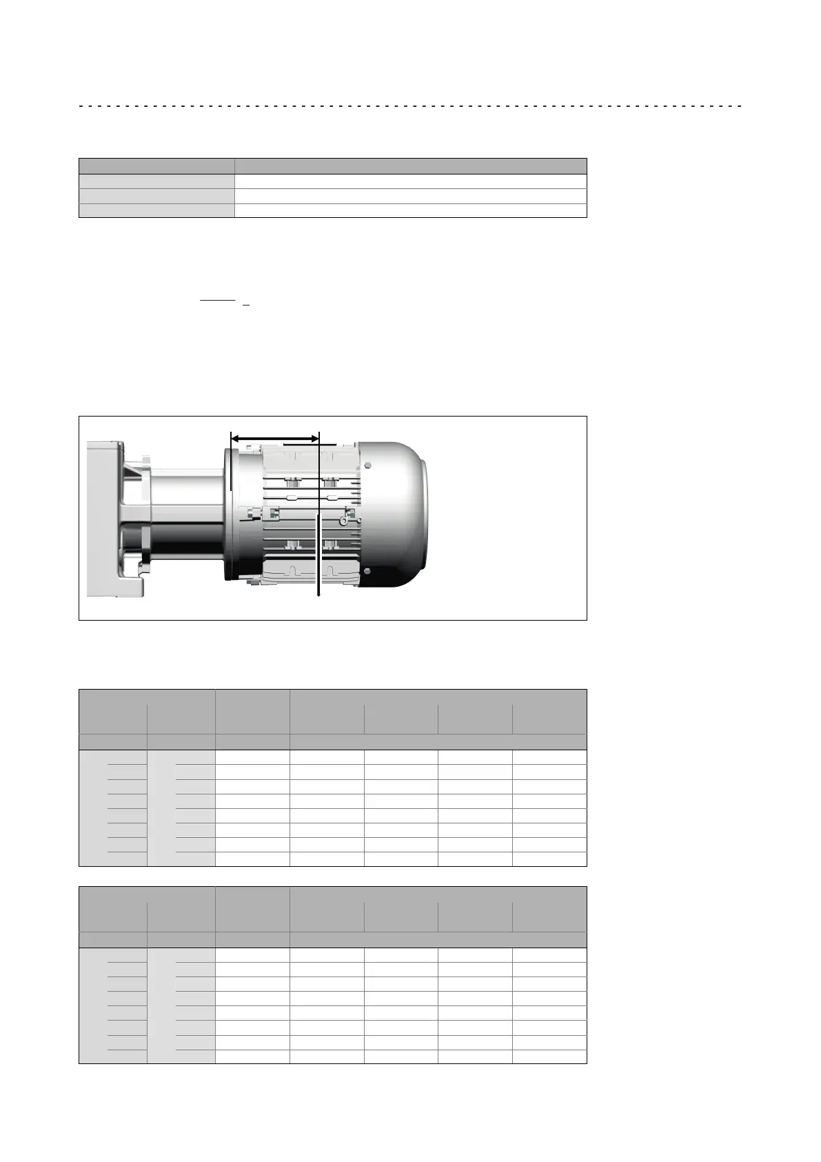
Maximum permissible load at the motor adapter
4
27
Lenze ¯ MA 12.0019 ¯ 6.1
Furthermore the loading case of the force F
M
has to be taken into consideration:
Loading case k
loading
case
Static 1
Dynamic−pulsating 0.8
Dynamic−alternating 0.6
The position of the motor‘s centre of gravity, including all motor options, must be
calculated. If the distance of the centre of gravity L
Tab
is greater, the permissible force
must be reduced as follows.
U = k x F x k x F
Mzul Lasall MTab Lasall MTab
L
Tab
L
<
If forces act from several directions, e.g. in the case of a moving horizontal travelling
drive, the acting forces have to be added vectorially (e.g. vertical force due to weight plus
horizontal acceleration force).
F
Mperm
corresponds to the maximum value of the forces added vectorially!
L
F
M
If the permissible force F
Mperm
is exceeded, the motor has to be supported in a suitable,
distortion−free fashion!
Drive size
Distance L
Tab
of the motor
Gearbox type
IEC NEMA
g500−B110
G50BB111
g500−B240
G50BB124
g500−B450
G50BB145
g500−B600
G50BB160
[mm] Maximum permissible force F
M
Tab
[N]
N
xA/2B
A
A 80 350 350 350 350
1B − 80 450 600 800 800
xC 5C 115 450 600 800 800
xD 5D 115 450 660 1000 1500
xE 5E 145 −−−−− 660 1000 1500
xF − 145 −−−−− −−−−− −−−−− 1500
xG 5G 190 −−−−− −−−−− −−−−− −−−−−
xH xH 250 −−−−− −−−−− −−−−− −−−−−
Drive size
Distance L
Tab
of the motor
Gearbox type
IEC NEMA
g500−B820
G50BB182
g500−B1500
G50BB215
g500−B2700
G50BB227
g500−B4300
G50BB243
[mm] Maximum permissible force F
M
Tab
[N]
N
xA/2B
A
− 80 350 −−−−− −−−−− −−−−−
1B − 80 800 800 −−−−− −−−−−
xC 5C 115 800 800 −−−−− −−−−−
xD 5D 115 1500 1500 1500 1500
xE 5E 145 1500 1500 1500 1500
xF − 145 1500 1500 1500 1500
xG 5G 190 1700 1700 1700 1700
xH xH 250 −−−−− 2600 3500 3500