SM01M 18
11 SCL/SCM CONTROL WIRING DIAGRAMS
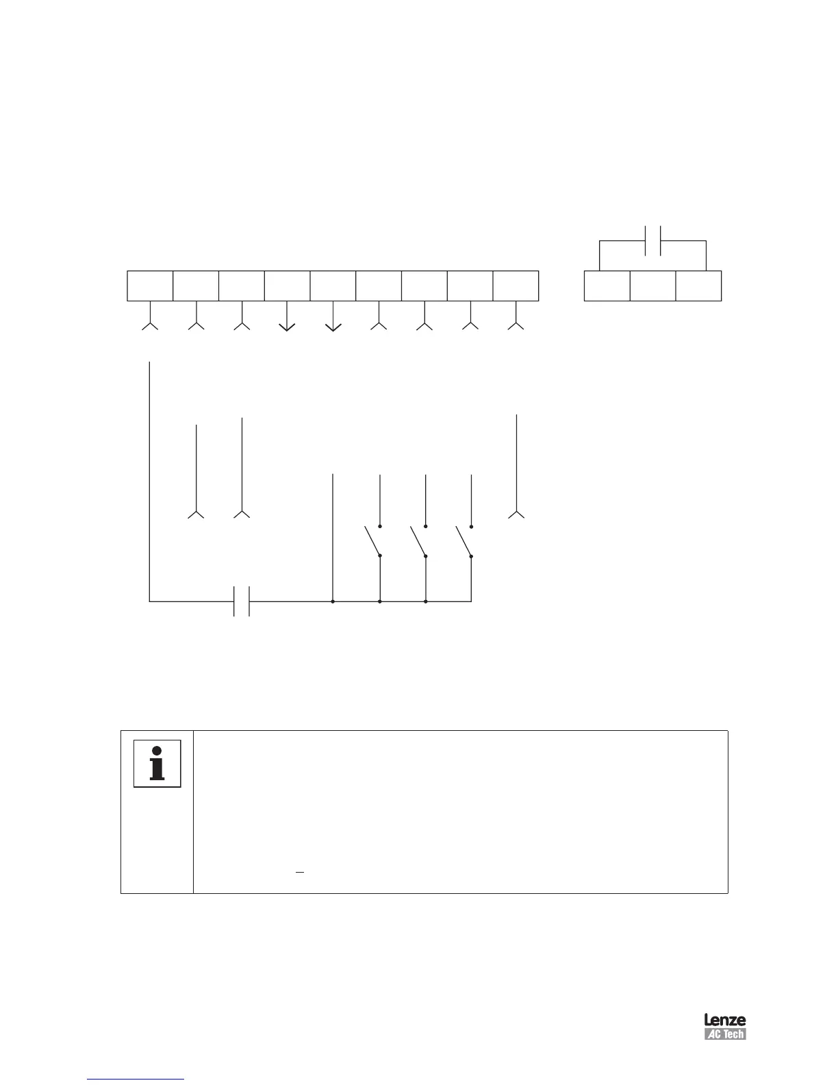
11.1 SCL/SCM Terminal Strip
Shown below is the control terminal strip, along with a brief description of the function of
each terminal. The following wiring diagram examples provide a quick reference to wire
the drive for the most common configurations.
SCL/SCM Terminal Strip
NOTE
• The function of terminals TB-13A, 13B, 13E and the Form A relay at terminals
16 and 17 are dependent on the programming of certain parameters.
Refer to Section 15, DESCRIPTION OF PARAMETERS.
• The digital inputs (terminals 1, 13A, 13B, and 13E) are active-high. They can
be activated using terminal 11 (which is +12 VDC) as shown in the following
diagrams, or by using an external voltage source with a range of +12 VDC to
+28 VDC (+ 10%).
 Loading...