8
Commissioning
Mounting
Base mounting
Secure the Advanced Tower Lamp with four M5 screws (2 N•m).
Flat mounting
Secure the Advanced Tower Lamp with two M5 screws (2 N•m).
Base mounting, hinged
15° angle increments
Angle adjustment screw
The angle of the module can be adjusted in intervals of 15 degrees in a range of
180 degrees, thereby enabling vertical, horizontal and inclined installation. Fas-
ten at the desired angle with the help of the built-in screw.
Electrical connection
Pin assignment
Press
Press to insert the wire.
Notes
• The white calotte and the buzzer cannot be controlled separately.
• The calottes can be arranged in any order.
Mounting calottes / buzzers
Place the calotte / buzzer on the bracket or the calotte underneath. Ensure that
the markings line up.
Rotate the calotte/buzzer clockwise to tighten
Note: The cover cannot be removed from the buzzer.
Technical data
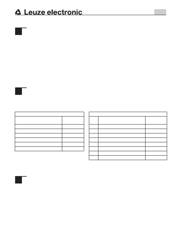
Cable pin assignment M12 connector pin assignment
Pin assignment
Conductor
color
Pin Pin assignment
Conductor
color
Light color: white / buzzer White 1 Light color: white / buzzer White
Light color: green Green 2 n.c. Brown
Light color: yellow/orange Yellow 3 Light color: green Green
GND Black 4 Light color: yellow/orange Yellow
Light color: blue Blue 5 GND Gray
Light color: red Red 6 n.c. Pink
7 Light color: blue Blue
8 Light color: red Red
Ambient temperature -10°C up to +60°C
Degree of protection IP66
Certifications c CSA us
PAL_A7-V1-BZ_de_en_fr_it_es_pt_zh_50138280-02.book Seite 8 Donnerstag, 22. August 2019 11:00 11

 Loading...

