Do you have a question about the Leuze electronic GS 61 and is the answer not in the manual?
Details the wiring and pinout for the 4-pin connector.
Details the wiring and pinout for the 3-pin connector.
Details the wiring and pinout for the 5-pin connector.
Provides details for cable connections.
Details physical dimensions and characteristics of the sensor.
Covers operating voltage, current, and output signals.
Information on housing, optics, and connection types.
Ambient temperature, protection class, and standards.
Lists part numbers for sensors with teach-in functionality.
Lists part numbers for sensors with potentiometer adjustment.
Describes normal operation and indicator status.
Details the initial teach-in process for sensor setup.
Explains how to configure output signal behavior.
Procedure for dynamic teach-in with moving label tape.
Procedure for static teach-in with stationary label tape.
Configures output signal for gap or label detection.
Describes logic levels for teach input and button operation.
Details the teach-in process for moving label tape.
Details the teach-in process for stationary label tape.
Explains light/dark switching adjustment via teach input.
Guidelines for cleaning the sensor's transparent parts.
Describes resistance to chemicals, solvents, and UV exposure.
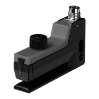
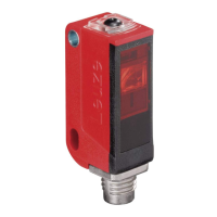
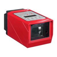
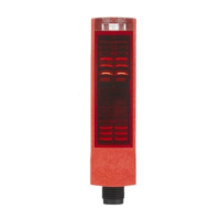
The Leuze electronic GS 61 is a forked photoelectric sensor designed for precise detection of labels on various base materials. Its compact and slim-line design, coupled with advanced features, makes it suitable for demanding industrial applications, particularly where space is limited or installation near the dispensing edge is required.
The GS 61 operates by emitting infrared light (940nm) across a 3mm mouth width to detect the presence or absence of labels within its fork. It can be configured to provide a switching signal either in the label gap or on the label itself, depending on the application requirements. The sensor utilizes a push-pull switching output, offering flexibility for both PNP and NPN logic.
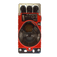
Sensitivity adjustment is a key feature, allowing for precise calibration to different label and base material combinations. This can be achieved through a multiturn potentiometer for manual fine-tuning or, in certain models, via a teach-in function. The teach-in process simplifies setup, enabling the sensor to learn the characteristics of the label and gap automatically, ensuring stable switching points.
The sensor's rapid response time of 50 µs and high switching frequency of up to 10 kHz enable it to handle high-speed applications, such as those found in labeling machines. It is designed to detect non-transparent labels on any given base material, making it a versatile solution for various packaging and production lines.
The GS 61 offers several features that enhance its usability and adaptability in industrial environments:
The GS 61 is designed for low maintenance, contributing to its overall cost-effectiveness and operational efficiency:
In summary, the Leuze electronic GS 61 is a robust and versatile forked photoelectric sensor, optimized for precise label detection in high-speed and space-constrained applications. Its combination of advanced sensing capabilities, user-friendly adjustment features, and durable design makes it a reliable choice for industrial automation.
| Brand | Leuze electronic |
|---|---|
| Model | GS 61 |
| Category | Accessories |
| Language | English |