Electrical connection
Leuze electronic MSI-MD-FBX 25
7 Electrical connection
WARNING
Faulty electrical connection or improper function selection may result in serious injury!
Ä Only allow qualified persons (see chapter 2.2 "Necessary competencies") to perform the
electrical connection.
Ä For access guarding, activate the start/restart interlock and make certain that it cannot be
unlocked from within the danger zone.
Ä Select the safety-relevant functions for the safety sensor. Observe the operating instructions
for the safety sensor.
Ä Always loop both safety-related switching outputs OSSD1 and OSSD2 of the muting con-
troller into the work circuit of the machine.
WARNING
Muting faults may result in serious injury!
Ä Connect the muting signals so that they are separated and protected and a short circuit be-
tween the cables is impossible.
NOTICE
Laying cables!
Ä Lay all connection cables and signal lines within the electrical installation space or perma-
nently in cable ducts.
Ä Lay the cables and lines so that they are protected against external damages.
Ä For further information: see EN ISO 13849-2, Table D.4.
NOTICE
Protective Extra Low Voltage (PELV)
The muting controller is designed in accordance with protection classIII for supply with PELV
(Protective Extra-Low Voltage).
NOTICE
Use in the USA and Canada
For use in the USA and Canada, use is only permitted in Class 2 circuits in accordance with the
NEC (National Electric Code).
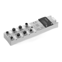
7.1 Connecting the muting controller
The muting controller is equipped with the following connections:
• One connection for the OSSDs of the safety sensor
M12 socket, 5-pin, A-coded
• A connection for the machine interface
M12 plug, 8-pin, A-coded
• Four connections for muting sensors 1…4
M12 socket, 5-pin, A-coded
• One connection for the reset button/acknowledgment unit
M12 socket, 5-pin, A-coded
• One connection for an external muting indicator
M12 socket, 5-pin, A-coded
• One service USB connection for reading out diagnostics
USB port of type Micro-B
 Loading...