Hardware Manual
11
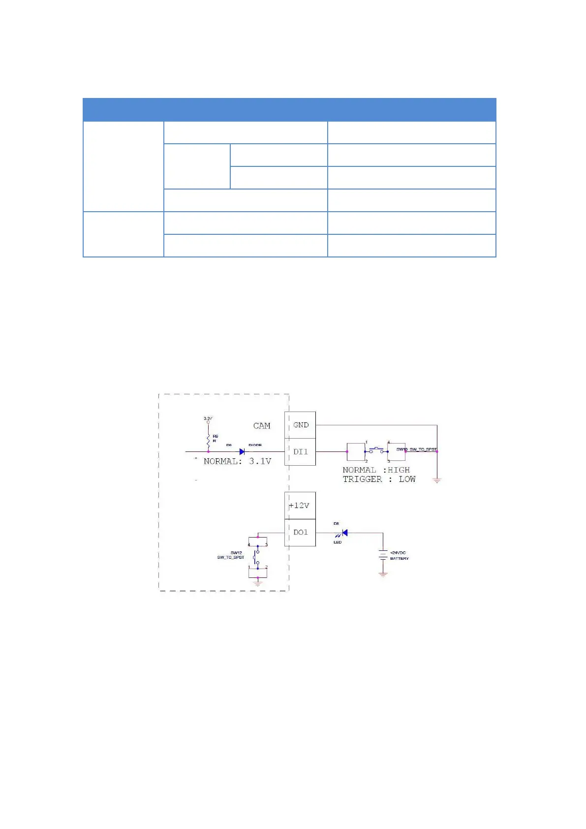
The table below shows the DI/DO connection specifications:
TTL - compatible logic levels
Logic level 1: 3.1V ~ 30V
Transistor (Open Collector)
Typical Connection
Based on these specifications, if the DI device has a voltage of 0V ~ 30V or the DO device has a
voltage of < 24V (< 50mA), then the camera can supply internal power to these devices and there
is no need to connect the DI/DO device to an external power source.
In this case, wire the connection as below. Use the DIO GND and DI pins to connect a DI device
and use the DIO PW and DO pins to connect a DO device. See wiring scheme below: