IMPORTANT: For 3-Way applications, note that one of the screw terminals
from the old switch being removed will usually be a different color (Black)
or labeled Common. Tag that wire with electrical tape and identify as the
Common (Line or Load) in both the dimmer wall box and remote wall box.
For non-standard wiring applications, refer
to Wire Connector and Conductor Size Chart
1 - #12 w/ 1 to 3 #14, #16 or #18
2 - #12 w/ 1 or 2 #16 or #18
1 - #14 w/ 1 to 4 #16 or #18
2 - #14 w/ 1 to 3 #16 or #18
WIRE CONNECTOR / # OF COND.
COMBINATION CHART
• Pull off pre-cut insulation from dimmer leads.
• Make sure that the ends of the wires from the wall box are straight
(cut if necessary).
• Remove insulation from each wire in the wall box as shown.
• For Single-Pole Application, go to Step 4a.
• For 3-Way Matching Remote (w/LEDs) Application, go to Step 4b.
Step 4b
TOOLS NEEDED TO INSTALL YOUR DIMMER
Slotted/Phillips Screwdriver Electrical Tape Pliers
Pencil Cutters Ruler
MULTI-DEVICE APPLICATION
In multi-dimmer installations, the reduction of the dimmer’s capacity may
be required. Refer to the chart for maximum load per dimmer.
NOTE: No derating is required for LED or CFL bulb applications.
If installing the device in a single device application, proceed with the
INSTALLING YOUR DIMMER section. If installing Dimmer in a
multi-device application, proceed as follows:
INSTALLING DIMMER BY ITSELF
OR WITH OTHER DEVICES
Changing the color of your Dimmer:
Your device may include color options. To change color of the face
proceed as follows:
1
2
Insert top tabs and
press in bottom tabs
to attach
Push in sides at bottom
tabs and pull outward to
release
INSTALLING YOUR DIMMER
NOTE: Use check boxes when Steps are completed.
ONOFF
ONOFF
ONOFF
ONOFF
ONOFF
ONOFF
ONOFFONOFF
ONOFF
ONOFF
ONOFF
ONOFF
WARNING: TO AVOID FIRE SHOCK OR DEATH; TURN
OFF POWER at circuit breaker or fuse and test that power
is off before wiring!
Step 1
Step 2
Identifying your wiring application (most common):
NOTE: If the wiring in your wall box does not resemble any
of these configurations, consult an electrician.
2
4
3
1
Single Pole
1. Line (Hot)
2. Neutral
3. Ground
4. Load
3-Way
1. Line or Load
(see important
instruction)
2. Neutral
3. Ground
4. First Traveler – note color
5. Second Traveler – note color
2
4
1
5
3
Cut
(if necessary)
5/8"
(1.6 cm)
Strip Gage
(measure bare
wire here)
Preparing and connecting wires:
Pull off pre-cut insulation from dimmer leads. Make sure that
the ends of the wires from the wall box are straight (cut if
necessary). Remove insulation from each wire in the wall box
as shown:
Step 3
Yellow/Red
Single Pole Wiring Application:
Step 4a
MAXIMUM BULB WATTAGE
Low-voltage dimmers are rated in Volt-Amps (VA). The maximum bulb wattage
is determined by the efficiency of the transformer in the low-voltage lighting
system. Transformer efficiencies will vary from different manufacturers;
consider 80% efficient as average. Use the chart to determine maximum bulb
wattage for typical transformer efficiency ratings.
MAXIMUM BULB WATTAGE
Mark 10
®
Powerline dimmers are rated in Volt-Amps (VA). The maximum bulb
wattage is determined by the efficiency of the Mark 10
®
Powerline ballast. The
following table shows the maximum number of ballasts that can be connected
to a single dimmer for different Mark 10
®
Powerline ballasts. Also note that the
table shows maximum ballasts for multi-gang installations.
Lutron Tu-Wire
®
:
To determine total ballast load, add the line current found on the ballast label
for all ballasts in the circuit. This will indicate the total load for the control.
Remove all
inner side
sections
Do not
remove
outer side
sections
Bend back and
forth to remove
side section
MAXIMUM LOAD PER DIMMER FOR MULTI-DEVICE
More than 2 Devices
700W
700VA
Two Devices
800W
800VA
Single
1000W
1000VA
Load
Incand
Mag LV
MAXIMUM BULB WATTAGE AT 75% EFFICIENCY
More than 2 Gang
560W
Rating
1000VA
Single
800W
Two Gang
640W
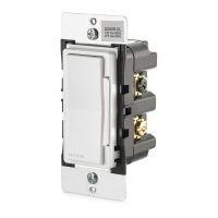
INTRODUCTION
L
eviton’s Decora Smart
TM
Z-Wave
®
Dimmers are designed to
communicate with each other via Radio Frequency (RF) to provide
remote control of your lighting. In a Z-Wave
®
network, each device is
designed to act as a router. These routers will re-transmit the RF signal
from one device to another until the intended device is reached. This
ensures that the signal is received by its intended device by routing the
signal around obstacles and radio dead spots. This dimmer is compatible
with any Z-Wave
®
enabled network, regardless of the manufacturer and
can also be used with other devices displaying the Z-Wave
®
logo.
WARNING: TO AVOID FIRE, PERSONAL INJURY OR DEATH,
DO NOT USE the remote for the control of high power heating
appliances such as portable heaters. There can be some unexpected
consequences if not used with care. For example, an empty coffee pot
can be remotely turned on. If that should happen, your coffee pot could
be damaged from overheating. If an electric heater is turned on by
remote control while clothing is draped over it, a fire could result. This
device will not control lighting that is used with electronic low-voltage
and high frequency power supply transformers, nor high pressure
discharge lamps (HID lighting). This includes mercury-vapor, sodium
vapor and metal halide lamps.
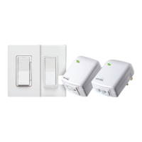
Decora
®
Smart Devices are ideal for living rooms, bedrooms, kitchens,
dining rooms, home offices, outdoor lighting or anywhere full control of
lighting is desired.
• Z-Wave Plus™ Certification
- Increased communication range
- Network Wide Inclusion
- Support for beaming and secure commands
- Over The Air (OTA) updates
• Compatible with Leviton Vizia RF+ systems
• Soft fade ON/OFF
• ON/OFF LED and Brightness level LED
• Three way communication
• Ease of installation - No new wiring
FEATURES
WIRING DIMMER:
Connect wires per WIRING DIAGRAM as follows:
WARNING: CONNECT A MAGNETIC LOW-VOLTAGE DIMMER ONLY
TO THE PRIMARY (HIGH-VOLTAGE) SIDE OF A MAGNETIC
LOW-VOLTAGE TRANSFORMER.
NOTE: The DZ1KD dimmer requires a Neutral wire connection.
• Green or bare copper wire in wall box to Green dimmer lead.
• Line Hot wall box wire to Black dimmer lead.
• Load wall box wire to Red dimmer lead.
• Line Neutral wall box wire to White dimmer lead.
• Yellow/Red dimmer lead should have Red insulation label affixed.
NOTE: If insulating label is not affixed to Yellow/Red dimmer lead, use
electrical tape to cover.
• Proceed to Step 5.
Cat. No. DZ1KD, 120V, For use with Advance Transformer
120V Mark 10
®
Powerline Electronic Ballasts
Max. # Ballasts/Dimmer for
Multi-gang
Advance
Mark 10
®
Powerline
Part No.
Lamp
Single
Gang
Two
Ganged
More than
2 Gang
REZ-2Q18-M2-LD
REZ-1T32
REZ-2Q26
REZ-1T32
REZ-1T42
REZ-1Q18-M2-BS
REZ-1Q18-M2-LD
REZ-2Q18-M2-BS
REZ-1T32
REZ-1T42-M2-BS
REZ-1T42-M2-LD
REZ-2Q26
REZ-2Q26-M2-BS
REZ-2Q26-M2-LD
REZ-1Q18-M2-BS
REZ-1Q18-M2-LD
REZ-2Q18-M2-BS
REZ-2Q18-M2-LD
REZ-1T42-M2-BS
REZ-1T42-M2-LD
REZ-2Q26-M2-BS
REZ-2Q26-M2-LD
REZ-1T42-M2-BS
REZ-1T42-M2-LD
REZ-2T42-M3-BS CFTR32W/GX24Q 13 10 8
CFTR32W/GX24Q 26 20 16
CFTR32W/GX24Q 26 20 16
CFTR26W/GX24Q 17 13 11
CFTR26W/GX24Q 17 13 11
CFTR26W/GX24Q 32 25 20
CFTR26W/GX24Q 32 25 20
CFTR18W/GX24Q 23 18 15
CFTR18W/GX24Q 23 18 15
CFTR18W/GX24Q 46 37 30
CFTR18W/GX24Q 46 37 30
CFQ26W/G24Q 17 13 11
CFQ26W/G24Q 17 13 11
CFQ26W/G24Q 17 13 11
CFQ26W/G24Q 32 25 20
CFQ26W/G24Q 32 25 20
CFQ26W/G24Q 32 25 20
CFQ18W/G24Q 23 18 15
CFQ18W/G24Q 46 37 30
CFQ18W/G24Q 46 37 30
CFM42W/GX24Q 20 16 13
CFM32W/GX24Q 26 20 16
CFM26W/GX24Q 17 13 11
CFM26W/GX24Q 32 25 20
151823CFM18W/GX24Q
WARNINGS AND CAUTIONS
• Dimmer may feel warm to the touch during normal operation.
• When magnetic low voltage circuits are operated at a dim level, with all lamps inoperative, excess current may flow through the transformer. To avoid possible transformer failure due to over
current, use a transformer that incorporates thermal protection or a fuse at the primary windings.
• Recommended minimum wall box depth is 2-3/4".
• Use this device with copper or copper clad wire only.
• Use with compatible dimmable LED, CFL bulbs, incandescent or 120V halogen fixtures only. For a list of compatible LED and CFL bulbs refer to www.leviton.com.
•
DO NOT mix bulb types when multiple bulbs are used with one dimmer. All bulbs shall be either LED; CFL or incandescent. Using the same make/model of each bulb will enhance dimmer performance.
• Leviton recommends Z-Wave
®
technology in residential installations up to 7,500 sq/ft. Metal junction boxes may adversely affect network coverage. Communication is designed to pass
through interior materials, exterior materials are designed to reflect RF energy and may prevent communication to detached buildings.
• Z-Wave
®
networking technology is designed for distributed communication. Large clustering of communicating devices in a centralized location (ie. a closet) is not recommended.
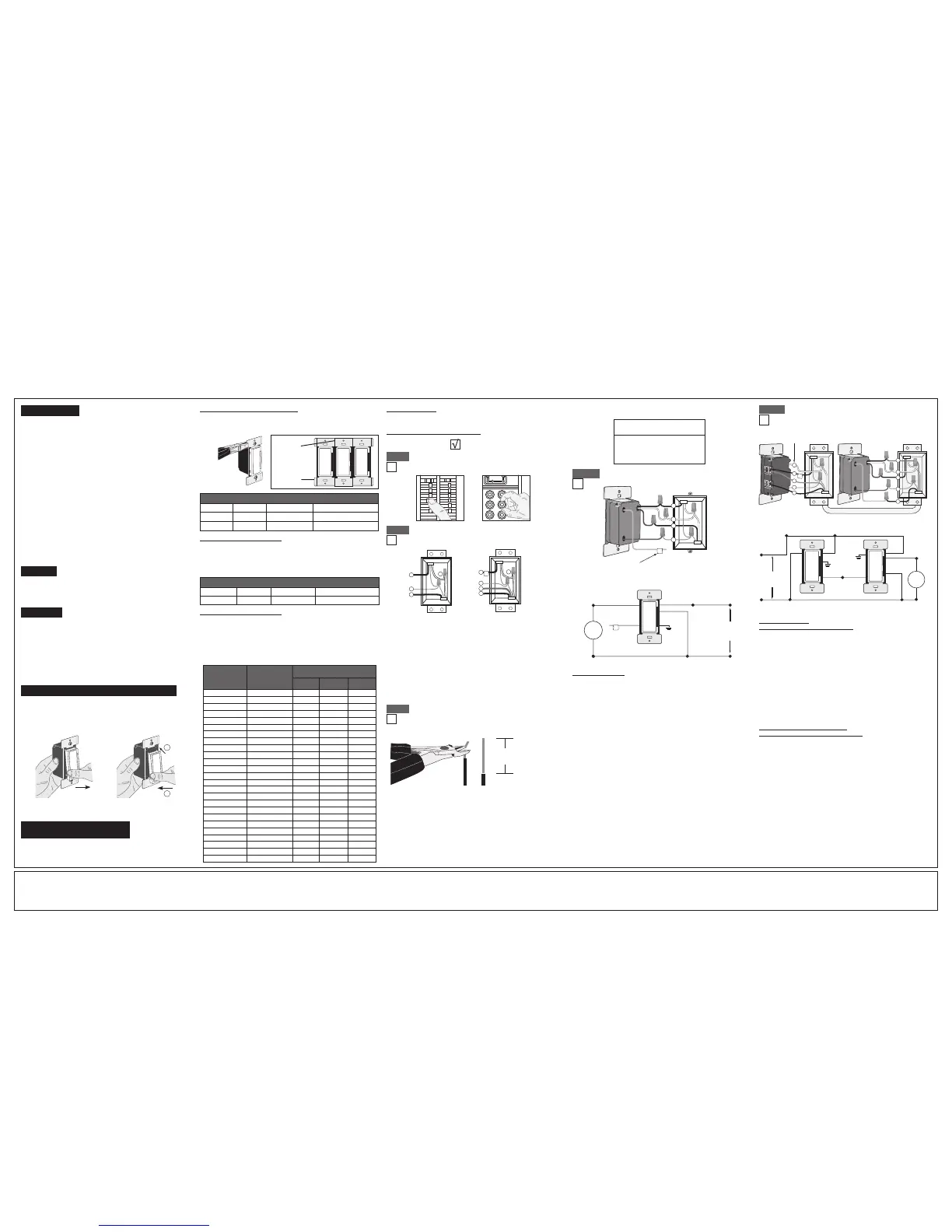
WIRING DIMMER
(wall box with load connection):
Connect wires per WIRING DIAGRAM as follows:
NOTE: The DZ1KD dimmer must be installed in a wall box that has a
Load connection and a Neutral connection.
• Green or bare copper wire in wall box to Green dimmer lead.
• Load wall box wire identified (tagged) when removing old switch to
Red dimmer lead.
• First Traveler Line Hot to Black dimmer lead.
• Remove Red insulating label from Yellow/Red dimmer lead.
• Second Traveler wall box wire (note color as above) to
Yellow/Red dimmer lead. This traveler from the dimmer must go to
the terminal screw on the remote marked "YL/RD".
• Line neutral wall box wire to White dimmer lead.
WIRING MATCHING REMOTE
(wall box with line hot connection):
Connect wires per WIRING DIAGRAM as follows:
NOTE: The matching remote must be installed in a wall box with a
Line Hot connection and a Neutral connection. A Neutral wire to the
matching remote needs to be added as shown.
NOTE: Maximum wire length from dimmer to all installed remotes
cannot exceed 300 ft (90 m).
• Green or bare copper wire in wall box to Green terminal screw.
• Line Hot (common) wall box wire identified (tagged) when removing
old switch and First Traveler to Remote terminal marked "BK".
• Second Traveler wall box wire from dimmer to remote terminal screw
marked "YL/RD" (note wire color). This traveler from the remote
must go to Yellow/Red dimmer lead.
• Line Neutral wall box to remote terminal screw marked "WH".
• Proceed to Step 5.
Hot (Black)
Additional Neutral Wire
White
Red
Green
Black
1
2
3
Yellow/Red
4
5
1
2
3
4
5
WARNINGS AND CAUTIONS
• TO AVOID FIRE, SHOCK, OR DEATH; TURN OFF POWER at circuit breaker or fuse and test that power is off before wiring!
•
TO AVOID FIRE, PERSONAL INJURY OR PROPERTY DAMAGE, DO NOT install to control a receptacle, a motor, or a transformer operated appliance.
• To be installed and/or used in accordance with electrical codes and regulations.
• If you are unsure about any part of these instructions, consult an electrician.
•
Use with magnetic low voltage transformers, incandescent, or 120V halogen fixtures only. Use a Leviton electronic low voltage dimmer to control electronic (solid state) low voltage transformers.
• Use ONLY with the appropriate Advance Transformer 120V Mark 10
®
Powerline or Lutron Tu-Wire
®
electronic ballasts for controlling the specific fluorescent lamps in Fluorescent Mode.
• When retrofitting Mark 10
®
Powerline dimming ballasts into fixtures that originally had Instant Start ballasts, the sockets MUST be replaced with Rapid Start sockets to allow proper
dimmer operation and prevent damage to the dimmer ballast. Refer to the instructions provided with the ballast.
•
The Decora
®
DZ1KD dimmer is not compatible with standard 3-way or 4-way switches. It must be used with up to 4
Decora
®
Digital DD00R-DL remotes for multi-location dimming
.
• Maximum wire length from dimmer to all installed remotes cannot exceed 300 ft.
• Save this instruction sheet. It contains important technical data along with testing and troubleshooting information which will be useful after installation is complete.
FCC COMPLIANCE STATEMENT
This device complies with Part 15 of the FCC Rules. Operation is subject to following two conditions: (1) this device may not cause harmful interference, and (2) this device must accept any interference received, including interference that may cause
undesired operation of the device. This equipment has been tested and found to comply with the limits for a Class B Digital Device, pursuant to Part 15 of the FCC Rules. These limits are designed to provide reasonable protection against harmful
interference in a residential installation. This equipment generates, uses, and can radiate radio frequency energy and, if not installed and used in accordance with the instructions, may cause harmful interference to radio communications. However, there
is no guarantee that interference will not occur in a particular installation. If this equipment does cause harmful interference to radio or television reception, which can be determined by turning the equipment OFF and ON, the user is encouraged to try
to correct the interference by one or more of the following measures:
IC COMPLIANCE STATEMENT
This device complies with Industry Canada licence-exempt RSS standard(s). Operation is subject to the following two conditions: (1) this device may
not cause interference, and (2) this device must accept any interference, including interference that may cause undesired operation of the device.
• Reorient or relocate the receiving Antenna.
• Increase the separation between the equipment and the receiver.
• Connect the equipment into an outlet on a circuit different from that to which the receiver is connected.
• Consult the dealer or an experienced radio/tv technician for help.
FCC CAUTION
Any changes or modifications not expressly approved by Leviton Manufacturing Co., Inc., could void the user’s authority to operate the equipment.
RATINGS
Incandescent - 1000W - 120VAC, 60Hz
LED/CFL - 450W - 120VAC, 60Hz
Mark 10
®
- 1000VA - 120VAC, 60Hz
 Loading...