Before Installation
• Requires installation into 2-7/8 in. - 3-1/4 in. diameter (73.025mm - 82.55mm)
mounting hole.
• Requires 4 in. (102mm) vertical clearance.
• When installation requires conduit for class 2 LumaCAN wiring, drill 2-7/8 in.
opening into side of junction box, and, install j-box above ceiling directly
above sensor.
• LumaCAN wiring requires Category rated cable for power and data.
Use Category 6 or better cable with quality RJ-45 connections. Wire per
TIA-568B standards.
• For compliance with Chicago Plenum requirements, installation in metal box
above ceiling is required. See the 3rd bullet point above.
• All LumaCAN wire segments must be tested and validated prior to power-up
of the system.
• The end of each LumaCAN network must be terminated for proper data flow.
A termination plug is pre-installed into one of the RJ-45 receptacles for this
Occupancy Sensor Technology
and Application Notes:
• This sensor uses microwave technology (5.8GHz frequency) to detect
motion. Microwaves are extremely sensitive, omni-directional and will
penetrate through most building construction materials. Microwaves do NOT
pass through metal and is the one material used to control the direction of
the microwave detection. When selecting a sensor location, ensure that
it is placed at least 6 ft away from any HVAC source as this technology is
sensitive to air movement.
• The OSR15-MCW sensor uses PIR detection technology. This technology
uses a lens which establishes dozens of zones of detection. The sensor
is sensitive to the heat emitted by the human body. In order to trigger the
sensor, the source of heat must move from one zone of detection to another.
The device is most effective in sensing motion across its field-of-view, and
less effective sensing motion towards or away from its field-of-view. Keep this
in mind when selecting the installation location. Note that occupancy sensors
respond to rapid changes in temperature, so care should be taken not to
mount the device near a climate control source (i.e. radiators, air exchanges,
and air conditioners). Hot or cold drafts will look like body motion to the device
and will trigger it if the unit is mounted too close. It is recommended to mount
the Occupancy Sensor at least 6 ft. away from a climate control source.
In addition, it is also recommended NOT to mount the Occupancy Sensor
directly under a large light source. Large wattage bulbs (greater than 100W
incandescent) give off a lot of heat and switching the bulb causes a temperature
change that can be detected by the device. Mount the Occupancy Sensor at
least 6 ft. away from large bulbs. If it necessary to mount the device closer,
lower the wattage of the bulb directly overhead.
• The field-of-view for this sensor is 750-1500 sq. ft. with the sensor located in the
middle of the desired detection area. Although the sensor provides full coverage
at maximum configured range, the field-of-view is more pronounced for half of
the detection area. The direction with the larger field-of-view is indicated by a
green dot on the inside face of the sensor. Please refer to the functional call out
diagram on the right.
WARNINGS
• TO AVOID FIRE, SHOCK, OR DEATH; TURN OFF POWER AT CIRCUIT
BREAKER OR FUSE AND TEST THAT POWER IS OFF BEFORE WIRING!
• To be installed and/or used in accordance with appropriate electrical codes
and regulations.
• If you are unsure about any part of these instructions, consult an electrician.
CAUTIONS
• ESD Sensitive Device: Use Safe handling procedures when installing.
• For indoor applications only.
• Save these instructions.
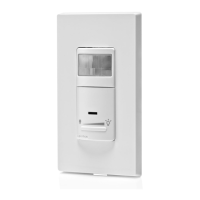
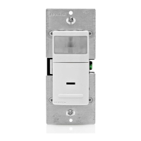
GreenMAX
®
DRC Sensor
Cat. No. OSR15-MCW
INSTALLATION AND QUICK START SHEET
ENGLISH
DI-000-OSR15-04B
SPECIFICATIONS
Input Voltage +12-24VDC, 90-45mA
IP Rating IP30
Network Connections
(2) RJ-45 Cat 6 or better for connection to LumaCAN network
1600’ Max Length per Daisy-Chain Segment.
Home-Run topology supported when using repeaters
Network length may be extended when using repeaters
Note: Pass-through RJ-45 connectors are prohibited from use on
Leviton project. Use of this connector style both voids all warranties
and voids any promise of product suitability of operation.
Operating Temperature 0-55°C, 0-85% relative humidity
Storage Temperature -10-85°C
Sensor Range 1500 sq. ft.
Sensor Technology PIR + Microwave + Photocell
Warmup Time 15 seconds
Patents
Patents covering this product, if any, can be found on
leviton.com/patents
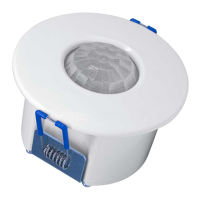
Product Description
This GreenMAX DRC Sensor is a direct network connected device which can
detect both Occupancy and Light level within its specified range. It reports
data using LumaCAN™ Sensor messages over the network, for receipt by any
Sapphire or GreenMAX DRC Room Controller.
LumaCAN
ON
PWR COM
ADDR
12345678
P1
P2
TERM
A
D
F
G
E
B
C
H
LumaCAN
COMPWR
P1
P2
TERM
ADDR
12345678
Reference
A. LumaCAN connections
B. Power indicator light
- Normal operation: SOLID [ON]
C. LumaCAN communication indicator light
- Normal operation: blinks when tx/rx LumaCAN communication is occuring.
D. Addressing DIP switches
E. Termination switch: [ON] to terminate (not used). Activating termination switch
when using plug will over-terminate the network and cause loss of data.
F. P1 universe programming DIP switch
G. P2 channel programming DIP switch
H. Occupancy sensor, light level sensor and occupancy indicator light
- Flashes: each time occupancy is detected
- Two blinks followed by pause (and repeat): when sensor does not have
an address assigned
- Occupancy: blinks RED when detected. When sensor does not have an
address assigned, it repeats two rapid blinks, followed by a pause.
Dot on side of
sensor indicates
centralized direction
of more pronounced
field-of-view
purpose. If this is the end of the network, only one of the RJ-45 receptacle will
be used. Leave the termination plug in the unused RJ-45 receptacle. If this is in
the middle of the network, both RJ-45 receptacles will be required. Remove and
discard the termination plug. If you have misplaced your termination plug, you
can terminate the end-of-run device by turning "on" the termination switch (E).