EasyManua.ls Logo

Leviton Decora IPV02 - User Manual

Leviton Decora IPV02
2 pages
Print Icon
To Next Page IconTo Next Page
Loading...
WARNINGS AND CAUTIONS:
• Ifyouarenotsureaboutanypartoftheseinstructions,consultanelectrician.
• Cleanoutersurfacegentlywithdampclothonly.DO NOT usesoapsorcleaningliquids.
• Nouserserviceablecomponents.DO NOT attempttoserviceorrepair.
• UsethisdeviceWITH COPPER OR COPPER CLAD WIRE ONLY.
WARNINGS AND CAUTIONS:
• TO AVOID FIRE, SHOCK, OR DEATH; TURN OFF POWER AT CIRCUIT BREAKER OR FUSE AND TEST THAT THE
POWER IS OFF BEFORE WIRING!
• Tobeinstalledand/orusedinaccordancewithelectricalcodesandregulations.
• Toavoidoverheatingandpossibledamagetothisdeviceandotherequipment,DO NOTinstalltocontrolareceptacle.
• DO NOT controlaloadinexcessofspeciedratingsoryoumaydamageproperty,orcauseinjuryordeath.
RESET
RESET
TEST
TEST
1 2
0 3
Push down tabs per
diagram, one at a time and
rotate forward to release
1 2
0 3
1 2
0 3
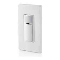
Attach new face by inserting
bottom hinge tabs, then pivot
and snap the color kit to attach
Tools needed to install your Device
Changing the color of your device
Slotted/PhillipsScrewdriver ElectricalTape Pliers
Pencil Cutters Ruler
INSTALLING YOUR DEVICE
NOTE: UsecheckboxeswhenStepsarecompleted.
ONOFF
ONOFF
ONOFF
ONOFF
ONOFF
ONOFF
ONOFFONOFF
ONOFF
ONOFF
ONOFF
ONOFF
Step 1
WARNING:TO AVOID FIRE, SHOCK, OR DEATH;
TURN OFF POWERatcircuitbreakerorfuseandtest
thatpowerisoffbeforewiring!
2
4
3
1
Single-Pole
1. Line(Hot)
2. Neutral
3. Ground
4. Load
Step 2
Identifying your wiring application
(most common):
NOTE:Ifthewiringinthewallbox
doesnotresembleanyofthese
congurations,consultanelectrician.
WIRING SENSOR:
Connect wires per WIRING DIAGRAM as follows:
NOTE: Agroundconnectionisrequiredtooperate.Usethegroundwire
intheelectricalboxforgroundconnection.Ifthereisnogroundwire,
makesuretheelectricalboxisgroundedandattachthegroundwireto
theboxwithascrew.
• GreenorbarecopperwireinwallboxtoGreenterminalscrew.
• LineHotwallboxwiretoterminalscrewmarked"BK".
• Loadwallboxwiretoterminalscrewmarked"RD".
• ProceedtoStep5.
Hot (Black)
Neutral (White)
Red
Black
Black
White
LOAD
Line
120VAC, 60 Hz
Sensor
Green
Ground
BK
RD
Terminal
Screw marked
Red (RD)
2
Terminal
Screw marked
Black (BK)
4
1
3
Single Pole Wiring Application:
Step 4
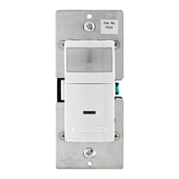
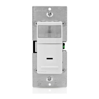
Single Pole Wide View Motion Activated Light Control
Cat. No. IPS02, IPV02 - INDOOR USE ONLY
Ratings:120VAC,60Hz-300WIncandescent-150WLED,CFL-200VAELV,MLV-Fluorescent2.5A-Resistive-1/6thHP
INSTALLATION INSTRUCTIONS
PK-93020-10-00-2A
FEATURES
• Cat.No.IPS02andIPV02haveasensingareaofcoverageof30ft.x
30ft.,andasensingangleof180
O
(seeSensingAreaCoveragegure
onpage2)
• Adjustablelightandtime-delaycontrolsarelocatedonthefrontofthe
device.Seeadjustmentsettingsectiononpage2fordetails.
• LEDindicatorisusedtoalerttheuserofthestatusofthedevice.
• AdjustableTimeDelaysettingfor30seconds,5minutes,
15minutesand30minutes.
• Occupancysensorscanbeconvertedtovacancysensors.
See Adjustment Section page 2.
LOCATION / MOUNTING
Thedevicerespondstotemperaturechangesandcareshouldbetaken
whenmountingthedevice.DO NOTmountdirectlyaboveaheatsource,
inalocationwherehotorcolddraftswillblowdirectlyonthesensor,or
whereunintendedmotion(e.g.,hallwaytrafc)willbewithinsensor’s
eld-of-view.
Preparing and connecting wires:
Thisdevicecanbewiredusingsidewireterminalscrews.
Chooseappropriatewirestrippingspecicationsaccordingly.
Strip Gage
(measure bare wire
here or use gage on
back of the sensor)
5/8”
(1.6 cm)
Cut
(if necessary)
Side Wire Connection
Sidewireterminalsaccept#14-12
AWGsolid copper wire only.
Step 3
Back Wire
Backwireopeningsuse#14-12
AWGsolid copper wire only.
BK
RD
YL 3-Way
Yourdevicemayincludecoloroptions.Tochangecoloroftheface
proceedasfollows:
• Makesurethattheendsofthewiresfromthewallboxarestraight
(cut if necessary).
• Removeinsulationfromeachwireinthewallboxasshown.
Question and Answer IconNeed help?

Do you have a question about the Leviton Decora IPV02 and is the answer not in the manual?

Summary

Safety and Product Information

General Warnings and Cautions

Essential safety precautions and warnings for installation and use to avoid fire, shock, or death.

Tools and Features

Lists required tools for installation and highlights key product features like sensing area and controls.

Location and Mounting Guidelines

Provides guidance on optimal device placement to ensure proper sensor function and avoid interference.

Installation and Wiring

Wiring Application Identification

Identifies common wiring configurations for single-pole applications and advises consulting an electrician if unsure.

Wire Preparation and Connection

Details how to prepare wires and connect them using side wire terminals or back wire openings.

Single Pole Wiring Diagram

Illustrates the specific wiring connections for a single-pole application, including line, load, and ground.

Pre-Mounting Device Testing

Instructions for testing the device's function (auto-on, push-on) after wiring but before final mounting.

Device Mounting and Power Restoration

Steps for securely mounting the device in the wall box and restoring power to complete installation.

Operation and Adjustments

Device Operation Modes

Explains the automatic and manual operation for IPS02 and IPV02 models, including LED indicator function.

Adjustment Settings

Details how to adjust light sensitivity and time delay settings for optimal performance.

Technical Specifications and Support

Sensing Area Coverage

Provides diagrams illustrating the horizontal and vertical sensing coverage areas of the device.

Troubleshooting

Offers solutions for common issues such as lights not operating or not switching off correctly.

Warranty and Compliance

Covers FCC compliance statement and the limited 5-year warranty, including contact information.

Leviton Decora IPV02 Specifications

General IconGeneral
Model NumberIPV02
Voltage120 VAC
Load TypeIncandescent, LED, CFL
WiringSingle Pole or 3-Way
TechnologyPassive Infrared (PIR)
Field of View180 degrees
Detection Range900 sq. ft.
ColorWhite
CertificationscULus
TypeOccupancy Sensor
Maximum Load150W LED/CFL
Operating Temperature0°C to 40°C (32°F to 104°F)
MountingWall
Device TypeOccupancy Sensor

Related product manuals