Before Installation
• Requires installation into 2” (52mm) mounting hole.
• Requires 4” (102mm) vertical clearance
• Surface diameter is 2.5” (64mm)
• When installation requires conduit for class 2 LumaCAN wiring, drill 2”
opening into side of junction box, and, install j-box above ceiling directly
above sensor.
• LumaCAN Wiring requires Category rated cable for Power & Data. Use
Category 6 or better cable with quality RJ-45 connections. Wire per
TIA-568B standards
• For compliance with Chicago Plenum requirements, installation in metal
box above ceiling is required. See the 4th bullet point above.
• All LumaCAN wire segments must be tested and validated prior to
power-up of the system.
• The end of each LumaCAN network must be terminated for proper data
flow. A termination plug is pre-installed into one of the RJ-45 receptacles
for this purpose. If this is the end of the network, only one of the RJ-45
receptacle will be used. Leave the termination plug in the unused RJ-45
receptacle. If this is in the middle of the network, both RJ-45 receptacles
will be required. Remove and discard the termination plug. If you have
lost your termination plug, you may turn on the "TERM" Switch ("E" in
diagram below) to terminate. DO NOT have the termination plug and the
termination switch active as this will cause network not to operate.
WARNINGS
• TO AVOID FIRE, SHOCK, OR DEATH; TURN OFF POWER AT CIRCUIT BREAKER OR
FUSE AND TEST THAT POWER IS OFF BEFORE WIRING!
• To be installed and/or used in accordance with appropriate electrical codes and regulations.
• If you are unsure about any part of these instructions, consult an electrician.
CAUTIONS
• ESD Sensitive Device: Use Safe handling
procedures when installing.
• For indoor applications only.
• Save these instructions.
1. Drill a 2" (52mm) mounting hole
2. Push network wires through hole and connect to sensor.
If end of line, the sensor must be terminated by setting the Termination switch to [ON].
Installation
WARNING: TO AVOID FIRE, SHOCK, OR DEATH; TURN OFF POWER at
circuit breaker or fuse and test that power is off before wiring!
GreenMax
®
DRC Sensor
Cat. No. OSR05-ICW
INSTALLATION INSTRUCTIONS
ENGLISH
DI-000-OSR05-04B
SPECIFICATIONS
Input Voltage +12-24VDC, 70-35mA
IP
Rating IP32
Network Connections
(2) RJ-45 Cat 6 or better for connection to LumaCAN
network 1600’ Max Length per Daisy-Chain Segment.
Home-Run topology supported when using repeaters
Network length may be extended when using repeaters
Operating Temperature 0-55°C, 0-85% relative humidity
Storage Temperature -10-85°C
Certifications FCC Class B
Sensor Range 450sqft
Sensor Technology PIR
Warmup Time 15 seconds
Patents
Patents covering this product, if any, can be found on
leviton.com/patents
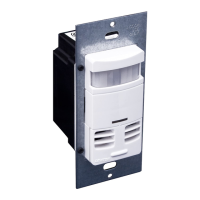
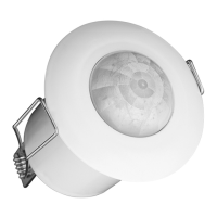
Product Description
This GreenMax DRC Sensor is a direct network connected device which
can detect both Occupancy and Light level within its specified range. It
reports data using LumaCAN™ Sensor messages over the network, for
receipt by any Sapphire or GreenMAX DRC Room Controller.
Reference
A. LumaCAN Connections
B. Power indicator light
- Normal Operation: SOLID [ON]
C. LumaCAN Communication indicator light
- Normal Operation: blinks when tx/rx LumaCAN
communication is occuring
D. Addressing DIP Switches
E. Termination Switch: [ON] to Terminate (not used.) Activating
Termination Switch when using plug will over-terminate the
network and cause loss of data.
F. P1 Universe Programming DIP switch
G. P2 Channel Programming DIP Switch
H. Occupancy Sensor, Light Level Sensor & Occupancy
indicator light
- Occupancy: blinks RED when detected. When sensor does
not have an address assigned, it repeats two rapid blinks,
followed by a pause.
LumaCAN
PWR
ON
COM
P1
P2
TERM
ADDR
12345678
A
D
F
G
E
B
C
H
LumaCAN
PWR
ON
COM
P1
P2
TERM
ADDR
12345678