WARNINGS AND CAUTIONS:
• Tobeinstalledand/orusedinaccordancewithappropriateelectricalcodesandregulations.
• Ifyouareunsureaboutanypartoftheseinstructions,consultaqualiedelectrician.
• Controllingaloadinexcessofthespeciedratingswilldamagetheunitandposeriskofre,electricshock,personalinjuryordeath.
Checkyourloadratingstodeterminesuitabilityforyourapplication.
• Donotinstallthisunittocontrolareceptacle.
WARNINGS AND CAUTIONS:
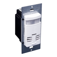
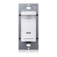
• TheOSSMT-GDOccupancySensorisintendedtoreplaceastandardsingle-poleDecorawallswitch.
• Donottouchthesurfaceofthelens.Cleanoutersurfacewithadampclothonly.
• Disconnectpoweratcircuitbreakerorfusewhenservicing,installingorremovingxture.
• Usethisdeviceonlywithcopperorcoppercladwire.WithaluminumwireuseonlydevicesmarkedCO/ALRorCU/AL.
SinglePole(OneLocation)orMulti-Location
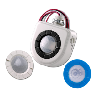
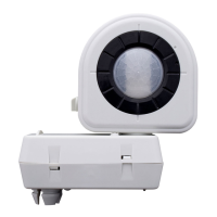
Multi-Technology Designer Wall Switch Occupancy Sensor
California Title 24 2005 Compliant
Cat. No. OSSMT-GD
Incandescent/Tungsten:800W@120VBallast:1200VA@120VBallast:2700VA@277VMotor:1/4hp@120V
Operating Temperature Range:0°Cto50°C
Relative Humidity:20%to90%non-condensing
No Minimum Load Required
Compatiblewithincandescentlamps,low-voltagelightingwithelectronicandmagnetictransformers,electronicandmagneticuorescentballasts,andfans.
INSTALLATION INSTRUCTIONS
TOOLS NEEDED TO INSTALL YOUR SENSOR
Slotted/PhillipsScrewdriver ElectricalTape
Pliers Cutters
SmallSlottedScrewdriver
• Leviton’sDecora
®
styledesign
• Sensorcanbegangedtogetherwithotherunitsinamultiple-switch
wallplate.
• Self-AdaptiveTechnologyadjuststooccupancypatternsofusein
autoadaptmode.
• TheAdaptingTime-outwalk-throughfeaturepreventslightsfrom
remainingONforanextendedperiodafteronlyamomentary
occupancy.
• Switchesasingleloadcircuit.
• OnePush-ButtonwhichprovidesmanualON/OFFswitchingat
anytime.
• Adjustablehorizontaleldofview.
• IntegratedphotocellpreventslightsfromturningONwhenroomis
adequatelyilluminatedbynaturallight.
• TrueZero-Crossrelayprovidesmaximumcontactlifeand
compatibilitywithelectronicballasts.
• Dualdetectiontechnology,bothPassiveInfraredandUltrasonic.
CanbeconguredasUltrasonicOnlybydisablingPassive
Infrared.
Leviton'sDesignerMulti-TechnologyWallSwitchOccupancySensor,
Cat.No.OSSMT-GD,isdesignedtodetectmotionusingthepassive
infrared(PIR)sensorfromsources(suchasapersonenteringa
room)withinitseld-of-view(monitoredspace)andautomatically
switchlightsON.TheOccupancySensorsensesmotionwithinits
maximumcoverageareaof2400sq.ft(223m
2
).Theultrasonic(US)
sensorsworkwiththePIRtokeepthelightsONwhenoccupied.The
controlledlightswillremainONuntilnomotionisdetectedandthe
scheduledtime-delayhasexpired,atwhichpointthelightswillbe
turnedOFF.Inadaptingtime-outmodethesensoradaptsitstime
delaysettingstotheoccupancypatternsofaroom.
TheCat.No.OSSMT-GDisanOccupancySensorthatisdesignedto
controlasinglelightingcontrolcircuitandprovidetheenergysavings
ofanoccupancysensor.Thisdevicedoesnotcontainaneutral
conductor.Itisintendedforuseinretrotapplicationswhereaneutral
isnotavailableinthewallbox.
TheOSSMT-GDisasinglerelaydevice,whichcanbeAutoONor
ManualON.ThedevicecontainsaphotocellthatprovidesanAmbient
LightHoldOfffunction.ThedeviceiscongurableforeitherUltrasonic
withPIRorUltrasonicOnlymodesofoperation.
Cat. No. OSSMT-GD is ETL listed, cETL listed and conforms to
California Title 24 requirements.
ThePIROccupancySensorusesasmallsemiconductorheatdetector
thatresidesbehindamulti-zoneopticallens.ThisFresnellens
establishesdozensofzonesofdetection.TheSensorissensitivetothe
heatemittedbythehumanbody.InordertoinitiallytriggertheSensor,
thesourceofheatmustmovefromonezoneofdetectiontoanother.
Thedeviceismosteffectiveinsensingmotionacrossitseld-of-view
anditislesseffectivesensingmotiontowardsorawayfromitseld-of-
view).Keepthisinmindwhenselectingtheinstallationlocation(refer
to Field-of-View diagrams).
TheUSOccupancySensorusesanon-audible,highfrequency(40kHz)
tosenseDopplershiftscausedbymotioninthespace.TheUSismore
sensitivetosmallmotionanddoesnotrelyonlineofsightfordetection.
Ifbothsensorshavenotdetectedanymotionforthesettimeoutperiod,
therelayanditscorrespondingloadwillbeturnedOFF.
Notethatoccupancysensorsrespondtorapidchangesintemperature,
socareshouldbetakennottomountthedevicenearaclimatecontrol
source(i.e.radiators,airexchanges,andairconditioners).Hotorcold
draftswilllooklikebodymotiontothedeviceandwilltriggeritiftheunit
ismountedtooclose.It is recommended to mount the Occupancy
Sensor at least 6 feet away from a climate control source.
Inaddition,itisalsorecommendedNOTtomounttheOccupancySensor
directlyunderalargelightsource.Largewattagebulbs(greaterthan
100Wincandescent)giveoffalotofheatandswitchingthebulbcauses
atemperaturechangethatcanbedetectedbythedevice.Mountthe
OccupancySensoratleast6ft.awayfromlargebulbs.Ifitisnecessary
tomountthedevicecloser,lowerthewattageofthebulbdirectly
overhead.
WARNING:TO AVOID FIRE, SHOCK, OR DEATH; TURN
OFF POWER atcircuitbreakerorfuseandtestthatpoweris
offbeforewiring!
Step 1
• Pulloffpre-cutinsulationfromsensorleads.
• Makesurethattheendsofthewiresfromthewallboxarestraight
(cut if necessary).
• Removeinsulationfromeachwireinthewallboxasshown.
Preparing and connecting wires:
9/16"
(1.4 cm)
Strip Gage
(measure bare
wire here)
Cut
(if necessary)
Step 3
INSTALLING YOUR SENSOR
NOTE:UsecheckboxeswhenStepsarecompleted.
Installing your Sensor – Single-Pole Application:
Step 4
Identifying your wiring application
(most common):
Step 2
WIRING SENSOR:
Connect wires per WIRING DIAGRAM as follows:Screwwireconnector
onclockwisemakingsuretherearenobareconductorsbelowthewire
connectors.Secureeachconnectorwithelectricaltape.
• GreenorbarecopperwireinwallboxtoGreenlead.
• LineHotwallboxwiretoBlacklead.
• LoadwallboxwiretoBluelead.
NOTE: Allow 1 minute for warm-up after connecting and energizing.
WIRING SENSOR 1:
Connect wires per WIRING DIAGRAM as follows:
• GreenorbarecopperwireinwallboxtoSensor1Greenlead.
• LineHot(common)wallboxwireidentied(tagged)whenremovingold
switchandFirsttravelerfromSensor2toSensor1Blacklead.
• SecondTravelerwallboxwirefromSensor2toSensor1Bluelead.
WIRING SENSOR 2:
Connect wires per WIRING DIAGRAM as follows:
• GreenorbarecopperwireinwallboxtoSensor2Greenlead.
• Loadwallboxwireidentied(tagged)whenremovingoldswitchand
SecondTravelerfromSensor1toSensor2Bluelead.
• FirstTravelerLineHotfromSensor1toSensor2Blacklead.
NOTE: Allow 1 minute for warm-up after connecting and energizing.
Step 5
NOTE:
TheCat.No.OSSMT-GDrequiresagroundwiretooperateproperly.
Ifthereisnogroundwire,ensureelectricalboxisgroundedandattach
groundwiretoboxwithascrew.Ifthegroundwireisoatingthisdevice
willnotwork.
NOTE:TheCat.No.OSSMT-GDrequiresagroundwiretooperate
properly.Ifthereisnogroundwire,ensureelectricalboxisgroundedand
attachgroundwiretoboxwithascrew.Ifthegroundwireisoatingthis
devicewillnotwork.
NOTE:Sensor1
must
beinstalledinawallboxthathasbothaLINEHot
andaGroundconnection.Sensor2
must
beinstalledinawallboxthat
hasbothaLoadandaGroundconnection.
Ifyouareunsureaboutanypartoftheseinstructions,consultaqualied
electrician.
NOTE:EithersensorcanturnthelightsON.Bothsensorsmusttimeout
toOFForbothmanualbuttonsmustbepressedforthelightstogoOFF
DESCRIPTION
DI-0XX-OSSMT-00A
FEATURES
NOTE:Dresswireswithabendasshownindiagramtorelievestress
whenmountingdevice.
•
Positionallwirestoprovideroominoutletwallboxfordevice.
• Partiallysecuredeviceusinglongmountingscrewsprovided.
• Restorepoweratcircuitbreakerorfuse.
NOTE: Allow 1 minute for warm-up after energizing.
NOTE:AllmodelsoftheOSSMT-GDarefactorypresettowork
withoutanyadjustments.Ifnecessary,adjusttheBlindersandPIR
RangeControltostopanyunwantedactivationofthelights(refer
to FEATURES section).
• ForadditionalTimeControlSettings(refer to the SETTINGS section).
NOTE:ToavoidPERMANENTDAMAGEtotheunit,becareful
NOTTOOVERTURNthecontrolknobsorleverswhensettingthe
Sensor.Thecontrolscanbeaccessedbyremovingthewallplate
(ifapplicable)andcontrolpanelcover(refer to Control Panel
Diagram).Useasmallstraightbladescrewdrivertoadjustknobs
andblinderlevers.
NOTE: DO NOT pressinonblinderleversoruseexcessiveforce
(refer to Control Panel Diagram).
• AttachtheControlPanelcoverwhenthedesiredsettingsare
complete.
If lights do not turn ON, refer to the TROUBLESHOOTING section.
Testing your Sensor prior to completely
mounting in wall box:
Step 6
NOTE: To access control settings, remove the control panel cover.
If necessary, remove the warning label that covers the adjustment
dials (refer to Control Panel Diagram).
Factory Settings:Thesensorisshippedfromthefactorytoworkin
almostallsituations,withoutanyaddedadjustments.Thefactorysettings
are:Blindersopen,10minutesxedTime-Out,LightsalwaysturnON
regardlessofexistinglightlevels,Mediumpassiveinfrared(PIR)range,
andHighUltrasonicrange.ThePIRandultrasonictechnologiesareboth
active.
Blinders:Theblindersaretwoindependentshuttersthatcannarrow
theeld-of-viewfromamaximumof180°downto32°.Theblindersare
operatedbymovingtheblinderleverstowardsorawayfromthecenterof
theSensor.Theblinderleverscanbefoundabovethecontroldialsinthe
controlpanel(refer to Control Panel Diagram).
Time-Outs:TheSensorhasthreetypesofTime-Outs:Fixed,Adapting,
andWalkthrough.
• FixedTime-Out:ThevalueofthisTime-Outisuserselected
throughtheuseoftheTimeControlSetting(refertoControlPanel
DiagramandTime-OutSettings).
FEATURES
Mounting
screws
(2 places)
Wall surface
Sensor