Do you have a question about the Leviton OSC10-M0W and is the answer not in the manual?
Essential safety precautions to prevent fire, shock, or death during installation.
Steps for preparing and connecting sensor wires for installation.
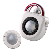
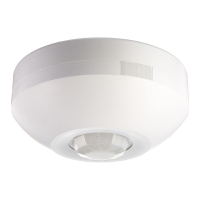
Detailed steps for mounting the sensor in a drop ceiling.
Instructions for mounting the sensor on wallboard or drop ceiling.
Guidance for installing the sensor using junction boxes or raceway.
Illustrates wiring connections for multiple sensors and a power pack.
Statement regarding FCC compliance and operational conditions.
Default mode where PIR turns lights on; either technology keeps them on.
Only one technology (PIR or ultrasonic) is active for motion detection.
Time before lights turn off after no motion is detected.
Feature for momentary occupancy, turning lights off shortly after leaving.
Indicator lights for motion detection, with option to disable.
Sensor analyzes motion signals to maximize detection and minimize noise.
Sensor adjusts delayed-off time based on room conditions and occupancy.
Sensor adjusts ultrasonic sensitivity based on learned occupancy patterns.
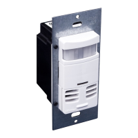
Recommended manual settings for knobs and switches.
Procedure to set delayed-off time to 6 seconds for walk testing.
Setting the ambient light override level for the photocell feature.
Diagnosing and resolving issues where lights fail to activate.
Troubleshooting constant lighting due to motion or sensor placement.
Addressing situations where lights remain on for an extended period.
Details of the warranty coverage and exclusions for the product.
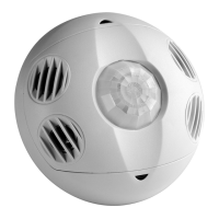
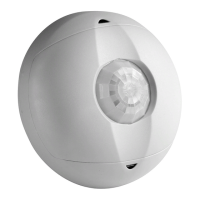
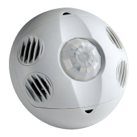
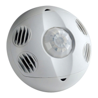
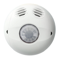
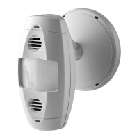
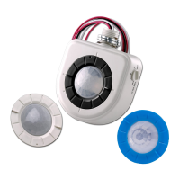
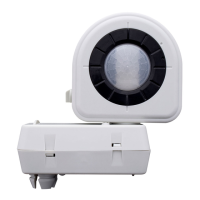
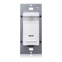
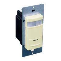
The Multi-Technology Ceiling Mounted Occupancy Sensor is a sophisticated low-voltage device designed to automate lighting control in commercial and residential settings. It integrates both infrared (IR) and ultrasonic technologies to detect occupancy, ensuring lights are turned on when a space is occupied and turned off when it's vacant, thereby contributing to energy savings.
The core function of this sensor is to detect motion and control lighting based on occupancy. It operates in conjunction with the OSPxx Series and CN100 power packs, which provide the necessary low-voltage power. When motion is detected, the sensor signals the power pack to turn on the lights. If no motion is detected for a specified "delayed-off time," the lights are automatically turned off.
The sensor offers two primary modes of operation:
A key feature is the Delayed-Off Time, which determines how long the lights remain on after the last detected motion. This time is adjustable via a knob on the sensor. The sensor also incorporates adaptive patterns that modify the delayed-off time based on environmental conditions and actual occupancy patterns, optimizing its performance over time.
The Walk-Through Mode is designed for transient occupancy. If a person enters a room and leaves within a short, predefined walk-through timeout (e.g., 2.5 minutes), the lights will turn off quickly. If the person stays longer, the sensor transitions to standard operation, adapting to longer occupancy periods.
LED Operation provides visual feedback on motion detection. Green flashes indicate ultrasonic motion detection, while red flashes signify infrared motion detection. This feature can be disabled if desired.
The sensor is equipped with advanced adaptive functions that allow it to continuously analyze motion detection signals and adjust its internal operation. This self-optimization minimizes false triggers caused by environmental factors such as electrical noise, air currents, and temperature changes, while maximizing accurate detection.
The sensor offers various settings and adjustments to tailor its performance to specific environments:
The device is designed for minimal maintenance.
| Sensor type | Passive infrared (PIR) sensor |
|---|---|
| Connectivity technology | Wired |
| Product color | White |
| Response time | 30 s |
| Input voltage | 24 V |
| Power source type | AC |
| Warranty period | 5 year(s) |
| Quantity per pack | 1 pc(s) |
| Operating temperature (T-T) | 0 - 40 °C |
| Operating relative humidity (H-H) | 0 - 95 % |
| Depth | 39.9 mm |
|---|---|
| Width | 106.68 mm |