FEATURES
• Fixture or electrical box mounted Passive Infrared Occupancy Sensor • Adjustable Time Delay • Optional peel and stick mask kit
• 20 ft. x 60 ft. aisle pattern at 40 ft mounting height • LED indicator light blinks when sensor detects motion
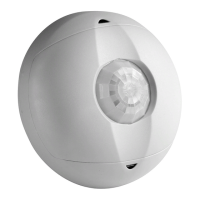
• 360° field-of-view for 20 ft. to 40 ft. mounting heights • 42" pre-stripped color coded wire leads
• Interchangeable 360° and aisle lens included • Offset Adapter (sold separately) positions sensor at optimum field-of-view
DESCRIPTION
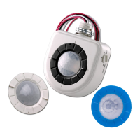
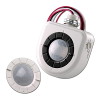
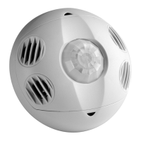
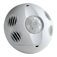
Leviton's High Bay Occupancy Sensors, Cat. No. OSFHU-ITW and OSFHU-CTW (cold storage), are specifically designed for high mounted areas such as warehouses, manufacturing and
other high ceiling applications. The OSFHB-xTW installs directly to an industrial luminaire or an electrical junction box. It is a self-contained sensor and relay that detects motion using the
passive infrared (PIR) to sense sources (such as a person entering a room) within its field-of-view (monitored space) and automatically switches lights ON. The controlled lights will remain ON
until no motion is detected and the scheduled time-delay has expired. The OSFHU-xTW is supplied with two, interchangeable lens rings that allows the user to select between a 360 degree
pattern or an aisle pattern.
Cat. No. OSFHB-ITW is UL listed, cUL listed and conforms to California Title 24 requirements. The Sensor's PIR lens is designed for 20 ft. to 40 ft. mounting heights for either symetrical
pattern or an aisle pattern which will provide coverage of 50' to 60' diameter (refer to Figures 4 and 5). The Sensor is sensitive to the heat emitted by the human body. In order to initially
trigger the Sensor, the source of heat must move from one zone of detection to another.
Note that occupancy sensors respond to rapid changes in temperature, so care should be taken not to mount the device near a climate control source (i.e. radiators, air exchanges, and air
conditioners). Hot or cold drafts will look like body motion to the device and will trigger it if the unit is mounted too close. It is recommended to mount the Occupancy Sensor at least 6 ft.
away from the heating or cooling ventilation source.
INSTALLATION INSTRUCTIONS
WARNING: TO BE INSTALLED AND/OR USED IN ACCORDANCE WITH APPROPRIATE ELECTRICAL CODES AND REGULATIONS.
WARNING: IF YOU ARE NOT SURE ABOUT ANY PART OF THESE INSTRUCTIONS, CONSULT A QUALIFIED ELECTRICIAN.
WARNING: CONTROLLING A LOAD IN EXCESS OF THE SPECIFIED RATINGS WILL DAMAGE THE UNIT AND POSE RISK OF FIRE, ELECTRIC SHOCK, PERSONAL INJURY OR
DEATH. CHECK YOUR LOAD RATINGS TO DETERMINE THE UNIT’S SUITABILITY FOR YOUR APPLICATION.
OTHER CAUTIONS AND NOTES:
1. DISCONNECT POWER WHEN SERVICING LUMINAIRE OR CHANGING BULBS.
2. USE THIS DEVICE WITH COPPER OR COPPER CLAD WIRE ONLY. WITH ALUMINUM WIRE USE DEVICES MARKED CO/ALR OR CU/AL ONLY.
3. DO NOT ATTEMPT TO DISASSEMBLE OR REPAIR. CLEAN OUTER SURFACE WITH A DAMP CLOTH ONLY.
TO INSTALL:
NOTE: The OSFHU-xTW is supplied with two lens trim rings. The 360 degree lens (white color trim ring) is installed at the factory with the aisle lens (black color trim ring) in the carton. Change
the lens for use in aisle applications. See below for changing lens trim ring. The OSFHU-xTW Sensor mounts in a 1/2" knock out hole on the end of a luminaire or an electrical box. The
Sensor’s field-of-view may be partially obstructed by the luminaire housing (refer to Figure 1A). At higher mounting heights, the outer beams are not used. As long as the bottom of the sensor
is mounted within 1" from the bottom of the luminaire, the field-of-view will not be affected (refer to Figure 1B).
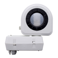
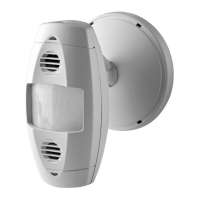
ADAPTER NOTE: For deep bodied luminaires or to clear other obstructions use Leviton's OSFOA-00W Adapter (refer to Figure 2A). The Adapter is designed to provide multiple mounting
positions to accommodate different mounting heights for optimum sensor positioning (refer to Figure 2B). Provided is a keyed, threaded snap-in nipple that holds the Adapter in place while
tightening the provided lock-nut. If the Adapter is needed, go to ADAPTER INSTALLATION section.
SENSOR INSTALLATION:
1. WARNING: TO AVOID FIRE, SHOCK, OR DEATH: TURN OFF POWER AT CIRCUIT BREAKER OR FUSE AND TEST THAT THE POWER IS OFF BEFORE WIRING.
2. The sensor comes with two lens rings, a white one for 360 degree detection (installed at factory) and a black one for aisle applications. NOTE: An optional peel and stick masking kit is
included. This circular adhesive label (with removable wedges) is applied to the OUTSIDE of the sensor lens. Use any number of wedges to alter field-of-view for your desired application.
3. To change lens, turn trim ring so that the two indented dots line up and and pull out by the finger tabs (refer to Figure 6A).
4. To insert the black aisle lens, line up the indented dots and indented tabs on underside of lens and insert into key openings and turn clockwise (refer to Figure 6B).
5. Line the finger tabs with the direction of the aisle. The lens will snap into indentation bumps to indicate the lens direction is at either 90 degree or 0 degree orientation.
6. Remove the lock-nut from the threaded nipple and insert the wires and the threaded nipple into a half inch hole of the luminaire body or the electrical box.
7. Slide the lock-nut over the wires and thread clockwise on to the threaded nipple to secure the sensor firmly in place making sure the lens is orientated towards the area to be monitored
(field-of-view) (refer to Figure 3).
8. Connect wires per Wiring Diagram as follows: BLACK lead to LINE (Hot); RED lead to LOAD; WHITE lead to LINE (Neutral). Twist strands of each lead tightly and, with circuit conductors,
push firmly into the appropriate wire connector. Screw connector on clockwise making sure that no bare wire shows below the connector.
9. Restore power at circuit breaker or fuse.
NOTE: Allow approximately 1 minute for charge-up. If the lights turn ON and the LED blinks when a hand is waved in front of the lens, then the Sensor was installed properly. If the operation is
different, refer to the Troubleshooting Section.
The Sensor is factory preset to work without any adjustments. If you desire to change the factory settings, refer to the SETTINGS section.
ADAPTER INSTALLATION:
1. Position one half of the Adapter body on the end of the luminaire to determine the appropriate mounting hole to be used on the Adapter that will position the sensor for optimum coverage.
The bottom of the sensor should be at or below the luminaire body (refer to Figure 2B).
2. Punch out the keyed hole of the Adapter half body to be mounted on the luminaire or electrical box (refer to Figure 1B).
3. Thread the provided lock nut part way on the keyed threaded nipple and insert through the keyed hole from the inside of the Adapter half body and snap into the half inch hole of the
luminaire or electrical box and tighten (refer to Figure 2A).
4. Punch out the non-keyed hole on the other Adapter body half and insert the wires and threaded nipple of the Sensor into the hole. Thread the provided lock nut on the nipple and tighten
positioning sensor towards the area to be monitored (refer to Figure 2A).
5. Feed the sensor wires through the keyed nipple attached to the luminaire or electrical box and connect per Wiring Diagram as follows: BLACK lead to LINE (Hot); RED lead
to LOAD;
WHITE lead to LINE (Neutral). Twist strands of each lead tightly and, with circuit conductors, push firmly into the appropriate wire connector. Screw connector on clockwise making
sure that no bare wire shows below the connector.
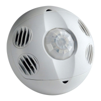
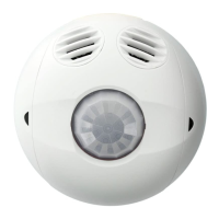
High Bay
Passive Infrared
Occupancy Sensor
and Offset Adapter
Cat. No. OSFHU-ITW (Sensor)
Cat. No. OSFHU-CTW (Cold Storage)
Cat. No. OSFOA-00W (Adapter, sold
separately)
Ratings:
800VA-6.67A @ 120VAC, 50-60Hz
1200VA-4.33A @ 277VAC, 50-60Hz
1500VA-4.32A @ 347VAC, 50-60Hz
– 40
o
F for Cat. No. OSFHU-CTW
Compatible with electronic and magnetic ballasts,
electronic and magnetic low-voltage ballasts
INSTALLATION INSTRUCTIONS
LIMITED 5 YEAR WARRANTY AND EXCLUSIONS
Leviton warrants to the original consumer purchaser and
not for the benefit of anyone else that this product at the
time of its sale by Leviton is free of defects in materials and
workmanship under normal and proper use for five years
from the purchase date. Leviton’s only obligation is to correct
such defects by repair or replacement, at its option, if within
such five year period the product is returned prepaid, with
proof of purchase date, and a description of the problem to
Leviton Manufacturing Co., Inc., Att: Quality Assurance
Department, 59-25 Little Neck Parkway, Little Neck,
New York 11362-2591. This warranty excludes and there
is disclaimed liability for labor for removal of this product or
reinstallation. This warranty is void if this product is installed
improperly or in an improper environment, overloaded,
misused, opened, abused, or altered in any manner, or is not
used under normal operating conditions or not in accordance
with any labels or instructions. There are no other or implied
warranties of any kind, including merchantability and
fitness for a particular purpose, but if any implied warranty
is required by the applicable jurisdiction, the duration of any
such implied warranty, including merchantability and fitness for
a particular purpose, is limited to five years. Leviton is not
liable for incidental, indirect, special, or consequential
damages, including without limitation, damage to, or
loss of use of, any equipment, lost sales or profits or
delay or failure to perform this warranty obligation. The
remedies provided herein are the exclusive remedies under
this warranty, whether based on contract, tort or otherwise.
PK-93439-10-00-5A
For Technical Assistance Call:
1-800-824-3005 (U.S.A. Only)
www.leviton.com
PK-93439-10-00-5A