INSTALLATION
1. Determine the best location for the sensor. Install the sensor at least
3 ft. away from uorescent ballasts and HVAC ducts, and at least
4 ft. away from incandescent xtures and HVAC diffusers. Install in
a standard NEMA single-gang box.
2. Cut a 2-1/2 in. diameter hole in the ceiling beneath the single-gang
box installed.
3. Remove approximately 5/8 in. (1.6 cm) of insulation from circuit wires.
4. Connect wires per appropriate WIRING DIAGRAM as follows: Twist strands
of each lead tightly and, with circuit conductors, push rmly into the
appropriate wire connector. Screw connector on clockwise making sure that
no bare wire shows below the connector. Secure each wire connector with
electrical tape.
5.
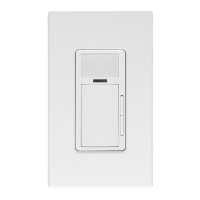
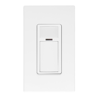
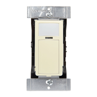
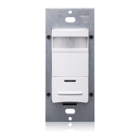
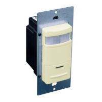
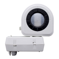
Remove the face plate and set it aside (see Figures 1A and 1B).
Set Time-Delay and Ambient Light as detailed in the SETTINGS section.
Mount unit to single-gang box using two screws provided. Replace face plate.
6. Restore power at circuit breaker or fuse.
SETTINGS
Time-Delay: Settings should be determined during the installation period.
This adjustment controls the amount of time the lights stay ON after the last
detected motion. You may select settings varying from 20 seconds (-) to 15
minutes (+) and any time in between.
NOTES:
• Allow approximately 40 seconds for initialization when powered up. If the
lights turn ON and the LED blinks when a hand is waved in front of the lens,
the sensor was installed properly. If the operation is different, refer to the
Troubleshooting Section.
• The ODC0S-I7 will have time settings varying from 20 seconds
to 30 minutes.
Ambient Light: This adjustment allows you to determine at what minimum
Ambient light level the device will operate. You may select settings from always
operating (day and night) to operating only when the Ambient Light level is less
than 3 lux, or anywhere in between. The lights will turn ON when the unit senses
motion and the Ambient Light reaches your desired level.
DI-000-ODC0S-02E
Self Contained Ceiling Mount Occupancy Sensor
Cat. Nos. ODC0S-I1, ODC0S-I2, ODC0S-I7
SPECIFICATIONS
Cat. No. ODC0S-I1
Rated: 120VAC, 60Hz
Incandescent: 1000W @ 120V
Inductive Fluorescent: 1000VA @ 120V
Power Consumption: 4W
Cat. No. ODC0S-I2
Rated: 220-240VAC, 50Hz
Incandescent: 1000W @ 220V
Inductive Fluorescent: 500VA @ 220V
Power Consumption: 4W
Cat. No. ODC0S-I7
Rated: 220-277VAC, 50/60Hz
Fluorescent: 2700VA @ 277V
Power Consumption: 4W
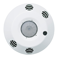
DESCRIPTION
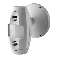
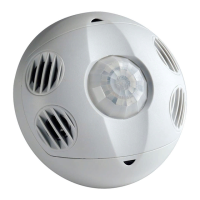
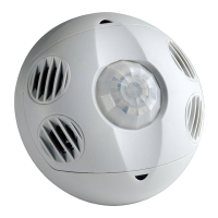
The Leviton Passive Infrared Ceiling Mount Occupancy Sensor, Cat. No.
ODC0S-I1, ODC0S-I7, ODC0S-I2 monitors rapid changes in temperature
within its eld-of-view (see Figures 2 and 3) and is designed to turn lights ON
when temperature changes (such as a person entering a room) is detected,
and OFF when occupancy is no longer detected and the scheduled time-delay
setting has expired.
Since Cat. No. ODC0S-I1, ODC0S-I7, ODC0S-I2 responds to temperature
changes, care should be taken not to mount the sensor directly above a heat
source, or where hot/cold drafts (i.e. from an HVAC duct) will blow directly on
the sensor, or where adjacent traffic, (i.e. hallway activity) will be within the
sensor’s eld-of-view.
In addition, it is also recommended NOT to mount the Occupancy Sensor
directly under a large light source. Large wattage bulbs (greater than
100W incandescent) give off a lot of heat and switching the bulb causes a
temperature change that can be detected by the device. Mount the Occupancy
Sensor at least 6 ft. away from large bulbs.
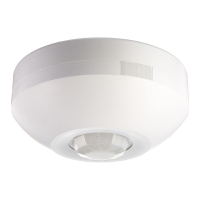
FEATURES
• Sensor has a 360° eld-of-view with 530 sq. ft. of coverage.
• LED indicator light blinks when sensor detects motion.
• Cat. No. ODC0S-I1, ODC0S-I7, ODC
Ø
S-I2 has four 14AWG 6"
pre-stripped color coded leads.
• Screw on cover plate shields mounting hardware and
adjustment control.
Perform the following steps for a more precise Ambient Light adjustment
(see Figure 3):
1. Make the adjustment when the actual ambient light is at the level where no
articial light is required.
2. Turn the Ambient Light adjustment to the (-) position (minimum light).
3. Turn the Time-Delay adjustment to the (-) position (at 20 seconds) and leave
the monitored space.
4. Re-enter the monitored space after the lights go OFF and the lights will
remain OFF.
5. Slowly turn the Ambient Light adjustment knob towards (+) until the lights
go ON.
6. Slightly turn the Ambient Light adjustment knob back towards (-) and leave
the monitored space.
7. When you return to the monitored space, the lights should remain OFF. If
the lights come ON, repeat step 6 until the lights remain OFF when you
re-enter the monitored space, at the desired ambient light level.
8. Reset the Time-Delay adjustment back to the desired position.
TROUBLESHOOTING
• Lights will not turn ON
- Circuit breaker or fuse is OFF: Turn the breaker ON. Ensure that
lights being controlled are in working order (i.e., working bulbs, integral
switches ON, etc.).
- Sensor is wired incorrectly or may be defective: Conrm that the
sensor’s wiring is done exactly as shown in the diagram and/or inspect it
visually for problems.
- Lens is dirty or obstructed: Inspect the lens visually and clean if
necessary, or remove the obstruction.
- Ambient light setting is for a darker background than that present:
Adjust the Ambient light setting.
• Lights will not turn OFF
- Sensor is wired incorrectly or may be defective: Conrm that the
sensor’s wiring is done exactly as shown in the diagram and/or inspect it
visually for problems.
- Sensor may be mounted too closely to an air conditioning or
heating vent, or traffic in an adjacent area is affecting sensor: Move
the sensor to another location, or close the vent.
- The line voltage has dropped: Perform the necessary tests to ensure
the line voltage has not dropped (beneath 100V for ODC0S-I1 or beneath
205V for ODC0S-I2 / ODC0S-I7). If it has dropped, check for operation of
any large appliances on the circuit, and turn them off.
- Light is being reected from an object: Check the area for any white
or shiny surfaces that might be reective, and correct
the situation.
• Lights turn OFF and ON too quickly
- Sensor may be mounted too closely to an air conditioning or
heating vent: Move the sensor to another location, or close the vent.
- Light being reected from an object: Check the area for any white or
shiny surfaces that might be reective, and correct the situation.
- Time delay set improperly: Adjust the TIME DELAY
(see SETTINGS section).
Figure 1A Figure 1B
INSTALLATION INSTRUCTIONS
ENGLISH
WARNINGS:
• TO AVOID FIRE, SHOCK OR DEATH: TURN OFF POWER AT CIRCUIT BREAKER OR FUSE AND TEST THAT THE POWER IS OFF
BEFORE WIRING!
• To avoid overheating and possible damage to this device and other equipment, DO NOT install to control a transformer-operated device(s)
other than appropriate low voltage lighting.
• To be installed and/or used in accordance with electrical codes and regulations.
• If you are not sure about any part of these instructions, consult an electrician.
CAUTIONS:
• No user serviceable components. DO NOT attempt to service or repair.
• Use this device WITH COPPER OR COPPER CLAD WIRE ONLY.