User Manual for BFS-i06
www.levitronix.com
PL-3502-00, Rev04, DCO# 24-054
This document and its content is confidential and the property of Levitronix
®
and shall not be reproduced, distributed,
disclosed or used for manufacturing or sale of Levitronix
®
products without the expressed written consent of Levitronix
®
.
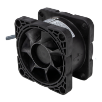
2.3 Basic Dimensions of Main Components
For other configurations, components or more details refer to the according drawings.
Figure 5: Basic dimensions in mm [in] of bearingless fan BFS-i06.1
Note: Non-tolerated dimensions are for reference only, dimensions in inch are rounded only
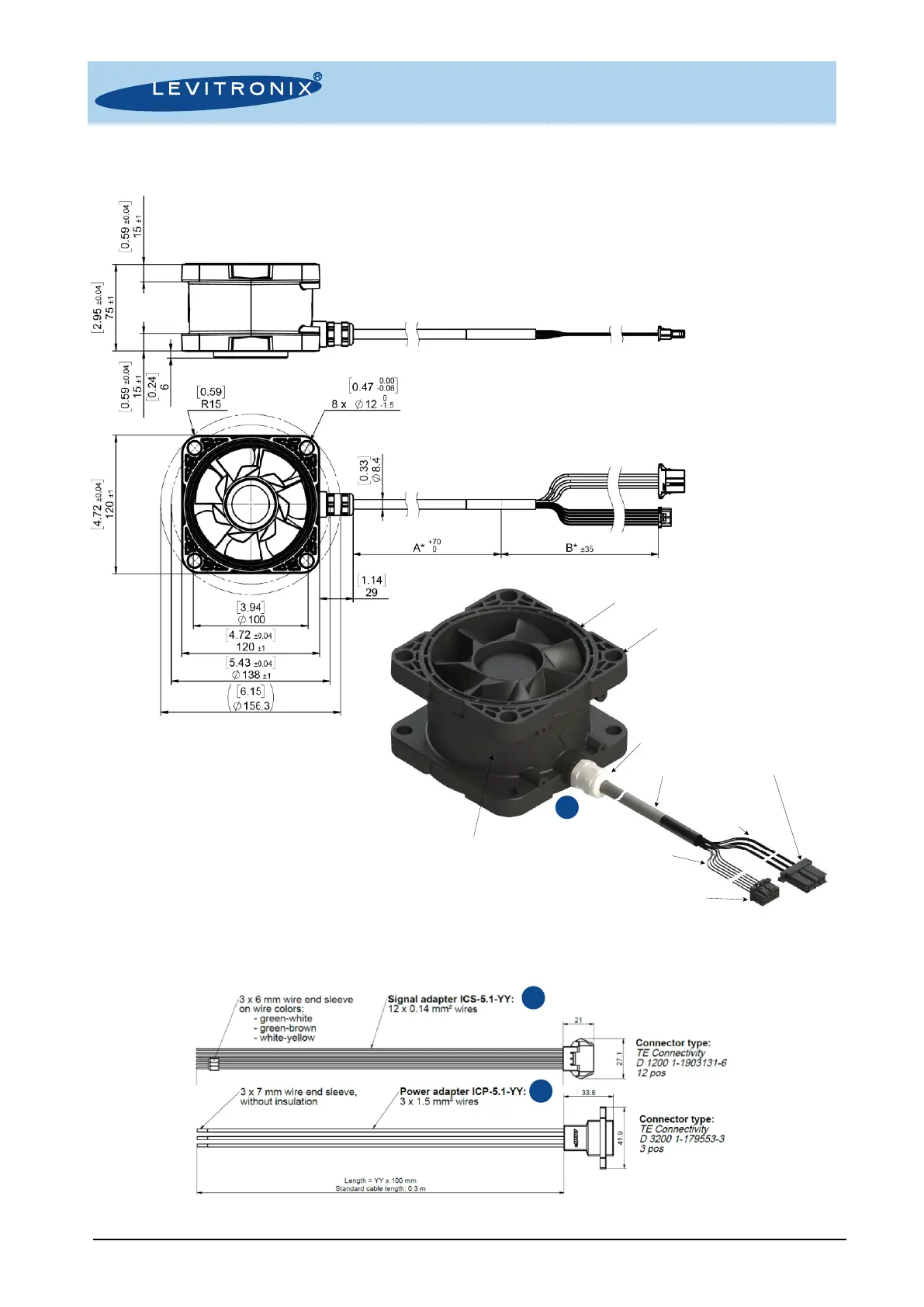
Figure 6: Basic dimensions of adaptor cables ICP-5.1-YY and ICS-5.1-YY
Minimum Cable Bending Radius:
Permanent Installation: 5 x cable OD (42 mm [1.65 in])
Sometimes Moved: 10 x cable OD (84 mm [3.31 in])
Cables are not suited for sustained dynamic bending and movement
Standard Cable Configuration:
A = 5.00 m [196.85 in]
B = 0.20 m [7.87 in]
Signal Wires
(PLC, RS485):
0.14 mm
2
, PVC
Connector Power:
TE D3200 1-178128-3
DC Supply
Power Wires:
1.5 mm
2
, PVC
Connector Signal:
TE D1200 1-1827864-6
Motor Cable:
PVC, gray
Cable Bushing:
PVDF with TPE-sealing
and FKM flat sealing ring
Housing and Rotor:
PP, electrically conductive,
flame retardant
Mounting Flange
Sealing Surface
 Loading...