6
Electric/Hydraulic Stern Thruster
Models 185TT, 250TT & 300TT
7
Electric/Hydraulic Stern Thruster
Models 185TT, 250TT & 300TT
1. Installation
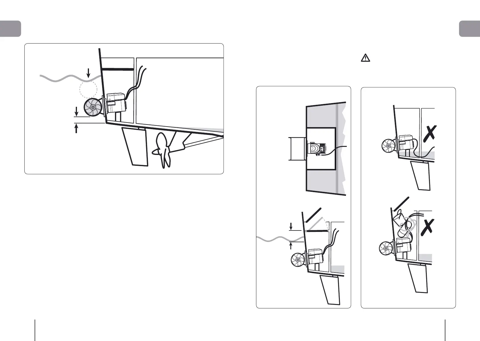
1.1 Choosing location
NOTE: This manual is to be read in conjunction
with the main manual supplied with the TT
Thruster, which has important information on
installation and use.
Ø = Tunnel Diameter.
For optimal performance the Thruster unit should
be mounted within the following:
• Chose position, ensure it is at least 1Ø below
the waterline to prevent air being sucked into
the tunnel.
• That the chosen area is flat.
• Check internal position is free of mechanical,
electrical or bulkhead obstructions.
1. Installation
Fig. 1.22
Fig. 1.11
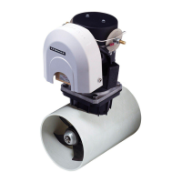
1.2 Internal structure
Fig 1.21
• The thruster must be in a watertight enclosure
that is a minimum of 150 mm (6”) above the
waterline. This space must also have adequate
ventilation. Access should be from above and the
entrance should not allow water in.
NOTE: Ensure all drainage ducts are sealed
and routed around the enclosure.
Fig. 1.21
Fig 1.22
The internal compartment must be watertight.
Do not use the compartment as storage.
1. Installation