1-2
Lexicon 480L Owner's Manual
Lexicon Digital
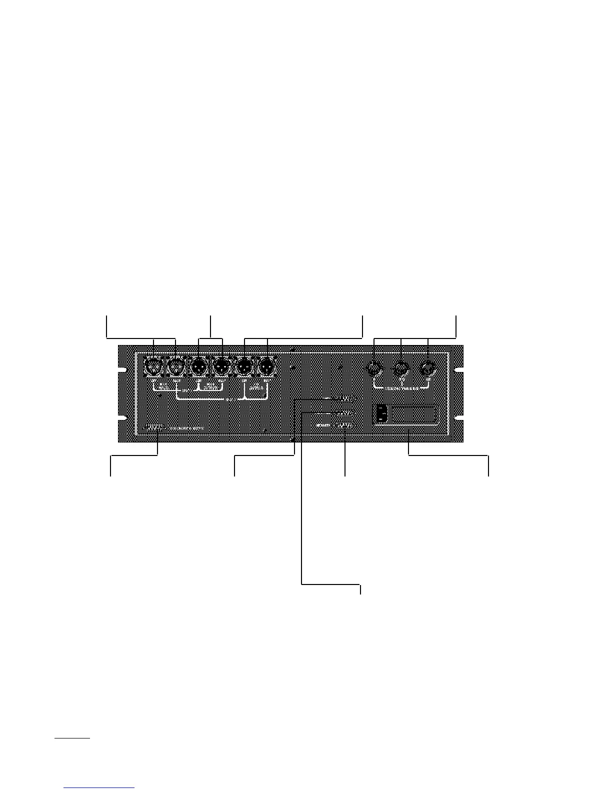
Audio I/O Connector
This DE9 connector
provides PCM 1610-
compatible digital I/O. It
has 18-bit word length
capability and can be
slaved to a 48 kHz, 44.1
kHz or 44.056 kHz
external word clock.
LARC 1 Connector
This DE9 connector
connects the mainframe to
the Lexicon Alphanumeric
Remote Control (LARC)
via a flexible 50-ft cable
(supplied)
Automation Connector
The Automation Connector
is provided for future
computer control and
automation features.
Important: Never connect
a LARC to this connector.
LARC 2 (Thru)
Connector
This DE9 connector allows
connection of a second
LARC. It also allows the
480L to be connected to a
224XL, with both units
under control of a single
LARC. A 10 ft cable is
available from Lexicon for
this application.
Power Connector and
Fuse Holder Cartridge
The Power Connector is a
standard 3-pin IEC power
connector. The Fuse
Holder Cartridge contains
the AC mains fuse(s). The
voltage changeover card is
also contained in this
compartment. Read
Appendix D for voltage
changeover information.
480L Rear Panel
Main Inputs (L & R)
The left and right Inputs
accept 3-pin male XLR
connectors. They are
electronically balanced
and (optionally) trans-
former isolated. Either pin
2 or pin 3 can be used as
high, but to maintain
polarity when transferring
data to the digital domain,
pin 2 should be high. Pin 1
and either pin 2 or pin 3 of
each input must be
grounded for unbalanced
operation. Input imped-
ance is 30 kilohms in
parallel with 100 pF. Inputs
accept input levels from +6
to +24 dBm.
Aux Ouputs (L & R)
The left and right aux
outputs are identical to the
Main Outputs, except that
they are used as second-
ary outputs when split or
cascade modes are
selected.
Important. Reversing
polarity on either input or
output connectors can
produce audible phase
inversion effects. Improper
phasing in the stereo path
can create a weak or thin
mix. Ensure that inputs
and outputs are wired
consistently.
Main Outputs (L & R)
The left and right Main
Outputs accept 3-pin
female XLR connectors.
They are electronically
balanced and (optionally)
transformer isolated. Either
pin 2 or pin 3 can be used
as high, but to maintain
polarity when transferring
data to the digital domain,
pin 2 should be high. Pin 1
and either pin 2 or pin 3 of
each output must be
grounded for unbalanced
operation. Output imped-
ance is 33 ohms, and
levels up to +24 dBm are
possible.
About the Rear Panel
MIDI Connectors
MIDI IN receives MIDI
information from other
MIDI-equipped devices.
MIDI THRU retransmits
MIDI information received
at the MIDI In connector,
without any change.
MIDI OUT is used to
transmit Automation data.

 Loading...