Hardware & Software Installation Instructions
Lexicon
6
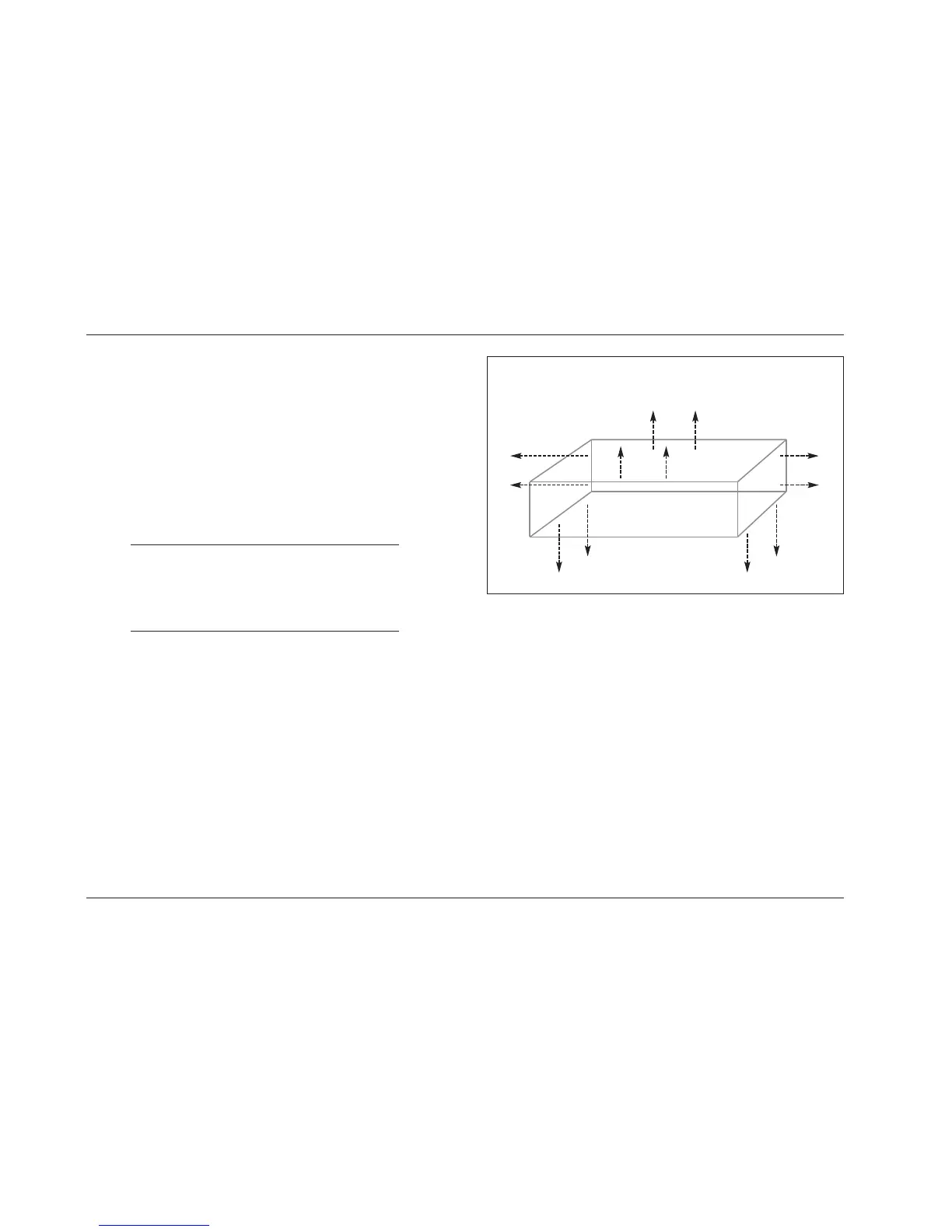
A-7. Position the MC-12 as shown in Figure III on the next page.
The numbered items that begin below correspond with the
numbers in Figure III.
1. The video boards are on the top.
2. The analog board is in the middle.
3. The main board is on the bottom.
4. The memory board is located on the right side of the
main board. The screw that secures the memory board
to the MC-12 chassis is identified with a white arrow.
5. The decoder board expansion slot is located on the left
side of the main board.
STEP A: INSTALLING THE HARDWARE
A-1. Make sure the MC-12 and all associated components are
powered off.
A-2. Disconnect the MC-12 from the electrical outlet and all
associated components.
A-3. Place the MC-12 on a flat, level surface such as a table or
workbench. Do not place the MC-12 on a surface that is
unstable or unable to support all four of its feet.
Note:
Work at a static-free workstation to avoid damaging
the EPROM. Damage resulting from failure to work
on a static-free surface might void the manufacturer’s
warranty or standard repair policies.
A-4. Use a 2.5mm Allen hex-head wrench to remove the twelve
2.5mm hex screws securing the MC-12 top cover. These
screws are identified in Figure II at the top of the next
column.
A-5. Remove the top cover from the MC-12 by sliding the top
cover toward the rear panel.
A-6. Put on the anti-static wrist strap included in the upgrade kit.
Figure II: Top Cover Screws
MC-12 Rear Panel
MC-12 Front Panel
 Loading...