Hardware & Software Installation Instructions
MC-12 Software Version 3.0
5
Serial Extension Cable
• DB-9 RS-232 connector (9-pin)
• Male-to-female straight-through cable
When the MC-12 is powered off with the rear panel power switch,
the male connector on the cable should be connected to the
RS-232 connector labeled 1 on the MC-12 rear panel. Then, the
female connector on the cable should be connected to the
appropriate connector on the computer. If this is a USB connector,
a USB-to-Serial port adapter is required. Refer to Figure I below for
more information about serial extension cable connections.
INSTALLATION INSTRUCTIONS
Completing the Software Version 3.0 installation process requires:
A. Installing new hardware in the MC-12
B. Installing the new software on a Personal Computer (PC)
C. Upgrading the MC-12
Note:
The new hardware must be installed before Software
Version 3.0 can be installed or the MC-12 can be
upgraded. Software Version 3.0 features are not
available unless the new hardware is installed.
Performing these steps is a straightforward process. But, to avoid
problems, carefully read and follow the instructions included in
this document. Pay particular attention to the Safety Summary
precautions on page 2, the Electrostatic Discharge (ESD)
Precautions on page 2, and other precautions included throughout
this document. Damage caused during installation might void
the manufacturer’s warranty or standard repair policies.
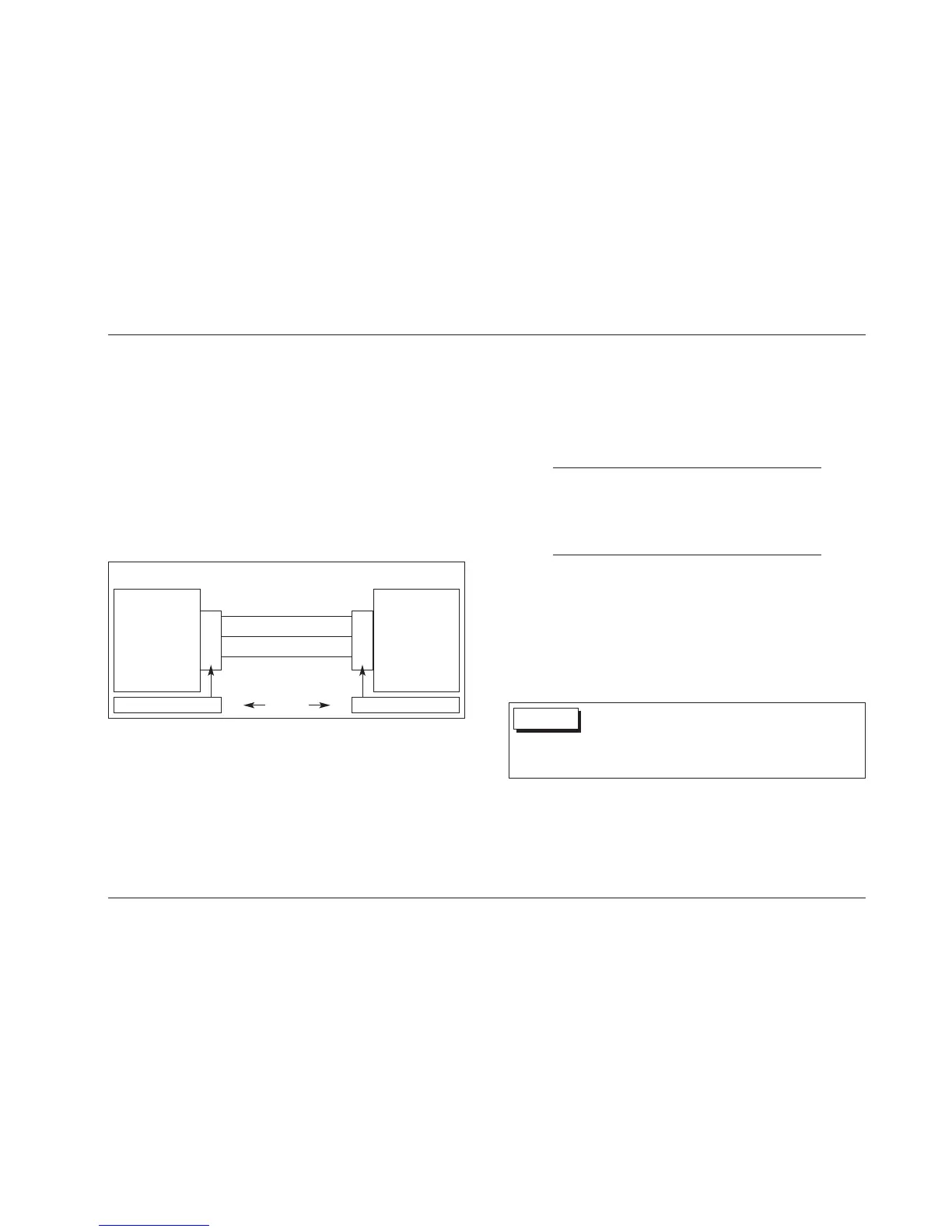
Figure I: Serial Extension Cable Connections
Wiring requirements for a 9-pin to 9-pin serial connection require a male-to-female
straight-through cable as shown in Figure I above.
MC-12 COMPUTER
2
3
5
2
3
5
Transmit Data
Receive Data
Ground
Receive Data
Transmit Data
Ground
9-pin D-shell (Male) Cable Ends
9-pin D-shell (Female)
• Never make or break connections to the MC-12 unless the
MC-12 and all associated components are powered off.
• Turn off and disconnect all power to the MC-12 prior to
installing the hardware upgrade.
WARNING
 Loading...