4
Y
35
1
2
Hardware & Software Installation Instructions
MC-12 Software Version 3.0
7
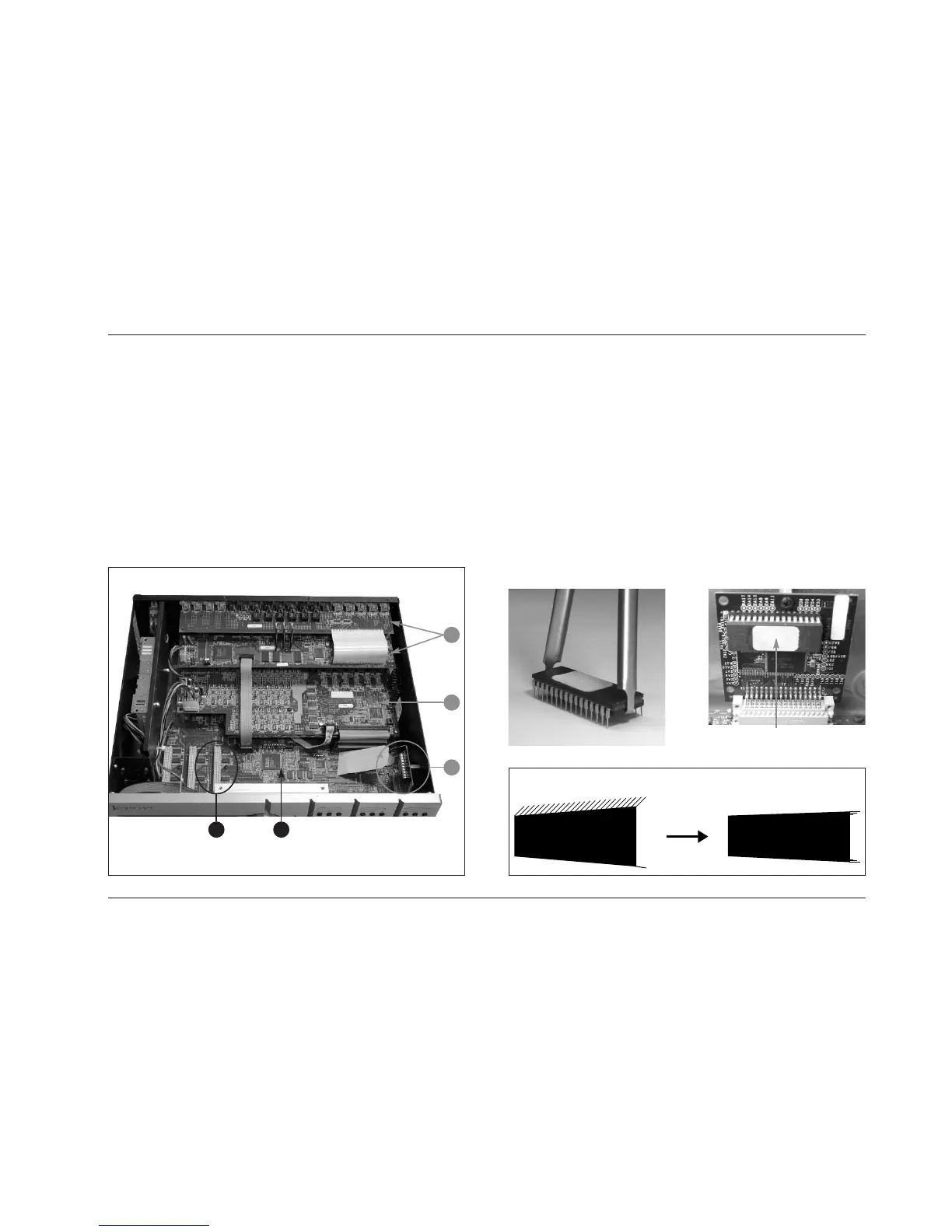
Figure III: MC-12 Interior
Figure V: Memory Board (Location U3)
Figure VI: Straightening EPROM Pins
Figure IV: IC Extractor Tool
Location U3
The numbers in the illustration shown above correspond with the numbered items in
step A-6 on the previous page.
A-8. Use a Phillips-Head screwdriver to remove the screw securing
the memory board to the MC-12 chassis. This screw is
identified with a white arrow in Figure III (below).
A-9. Disconnect the memory board from the main board. Then,
place the memory board on an anti-static surface.
A-10. Use the IC extractor tool as shown in Figure IV (below) to
remove the currently installed EPROM from location U3 on
the memory board. Location U3 is identified in Figure V
(below).
A-11. Examine the Software Version 3.0 EPROM included in the
upgrade kit. The manufacturing process sometimes leaves
EPROM pins slightly angled from the EPROM body. The pins
must be straightened before the EPROM is inserted.
To straighten the EPROM pins, place the EPROM on its side
on a flat, static-free surface. Exerting gentle pressure downward,
roll the EPROM as shown in Figure VI (below) to force the
pins into a position parallel to the surface.
. . . Step A: Installing the Hardware continues on page 8
 Loading...