58D6056 27
ON
OFF
OPTIONAL REMOTE
WALL SWITCH
PILOT
HI
LO
ON
OFF
TH
TP
TH/TP
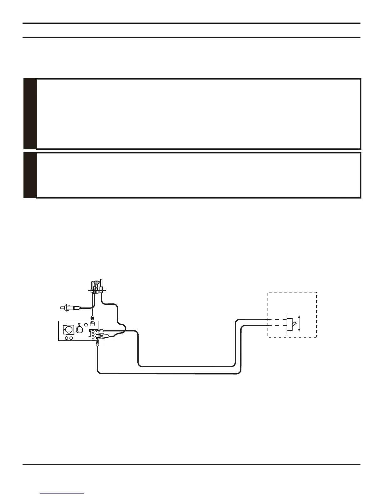
REMOTE WALL MOUNTED SWITCH
A remote wall switch and up to fifteen (15) feet of 18 Ga. wire may be used with this appliance. Attach the wall switch in
a junction box at the desired location on the wall. See Figure 34. Do not extend beyond the wall switch wire length pro-
vided.
NOTE: Extended lengths of wire may cause the fi replace not to function properly. Longer length of wire
is permitted if the wire is made out of larger gauge (diameter) wire. Always check with local code.
Figure 34 - Wiring Diagram for Wall Switch
ELECTRICAL INSTALLATION
ELECTRICAL WIRING
Electrical connections should only be performed by a qualifi ed, licensed electrician.
Main power must be off when connecting to main electrical power supply or performing
service. All wiring shall be in compliance with all local, city, and state codes. The
appliance, when installed, must be electrically grounded in accordance with local codes,
or in the absence of local codes, with the National Electrical Code ANSI/ NFPA 70 (latest
edition) and Canadian Electrical Code, CSA C22.1.
WARNING
Label all wires before disconnecting when servicing controls. Wiring errors can cause
improper and dangerous operation.
CAUTION
Verify proper operation after servicing.
This stove will work without any electrical supply. Electricity is only needed if you install a remote wall mounted switch.
NOTE: If installed in mobile home, stove must be bolted securely to fl oor.