Provide an adequate electrical connection for the sensor; refer to the wiring
schematics in the Section “Checking the Direction of Rotation”.
Systematically check for leaks after the installation, and before starting the
pump system.
Only C- and CC-type: Conduct a leak test before re-fitting the covers.
3.7.4 Gas Ballast Kit (option)
As options, LEYVACs can be retrofitted with an electrically (24 VDC) or a
manually operated gas ballast system. These conversion kits modify the con-
ventional rotor purge gas line (A). Via these systems ambient air as the gas
ballast can be supplied at a fairly high throughput of up to 80 Nl/m. The 24
VDC valve is nc.
With the LEYVAC LV 250 with installed gas ballast kit pumped / process
gas can leak into the pump’s surrounding area via the gas ballast port. Due
to the high compression inside the pump this is the case with inlet pres-
sures >150 mbar.
When pumping dangerous, flammable, or toxic gases the gas ballast kit of
the LEYVAC LV 250 must not be used!
The gas ballast conversion kit contains all of the necessary modification
parts.
Only C- and CC-type pumps: Remove the side cover.
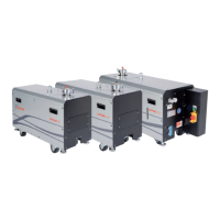
Fig. 3.16 LEYVAC with gas ballast kit installed (24 V)Fig. 3.15 Purge gas lines
Rotor Purge (A)
Purge (B)
WARNING
 Loading...