EasyManua.ls Logo

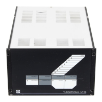
LEYBOLD TURBOTRONIK NT 20 User Manual

LEYBOLD TURBOTRONIK NT 20
28 pages
Go to English
To Next Page IconTo Next Page
Page #1 background imageLoading...
Page #1 background image
Vakuum-Lösungen
Applikations-
Unterstützung
Service
LEYBOLD VACUUM
TURBOTRONIK
NT 20
Elektronischer
Frequenzwandler
Electronic Frequency
Converter
Kat.-Nr. / Cat. No.
857 20/21/22
Operating Instructions
Gebrauchsanleitung
GA 05.208/12

Questions and Answers:

LEYBOLD TURBOTRONIK NT 20 Specifications

General IconGeneral
BrandLEYBOLD
ModelTURBOTRONIK NT 20
Inlet FlangeDN 16 ISO-KF
Outlet FlangeDN 16 ISO-KF
Operating Temperature+5 - +40 °C
Storage Temperature-20°C to 60°C
CoolingAir

Summary

Description

Design and Function

Details the purpose and functional design of the electronic frequency converter for driving turbo molecular pumps.

Standard Specifications

Lists the standard features, power linecord, fuses, and accessories included with the converter.

Technical Data

Provides electrical specifications, operating temperatures, dimensions, weight, and speed ratings for compatible pumps.

Ordering Data

Lists catalog numbers for the converter, connection lines, and optional accessories like mounting frames.

Connection

Setting the Mains Voltage

Explains how to change the mains voltage setting and the corresponding fuse adjustments for safe operation.

Connecting the TURBOVAC

Instructions for physically connecting the TURBOVAC to the converter using the appropriate line.

Connecting the Forevacuum Pump

Details how to connect the forevacuum pump to the relay contact output for automatic operation.

Connecting the Cooling

Describes connecting cooling systems (solenoid valve or fan) to the designated socket.

Connecting the Venting Valve

Covers connecting power failure airing valves or delayed venting devices for proper pump venting.

Connecting the Flange Heater

Instructions for connecting a flange heater for pumps with CF connection flanges.

Connecting the Remote Control Unit

Explains how to connect external control units via PLC signals or internal outlets for remote operation.

Installing the TURBOTRONIK

Provides guidelines for rack installation, emphasizing ventilation and heat dissipation requirements.

Operation

Start-up

Guides through initial setup, including DIP switch configuration and power-on sequence.

Start-up of the TURBOVAC

Details the process of initiating the TURBOVAC acceleration sequence via the START key and monitoring status LEDs.

Bake-out of the TURBOVAC

Explains the bake-out procedure, necessary for achieving low pressures, and the role of heating and cooling.

Operation

Describes normal operation, including LED indicators for speed, current, and the OVERLOAD mode.

Shut-down of the TURBOVAC

Outlines the procedure for safely shutting down the TURBOVAC and its associated components.

Venting of the TURBOVAC

Emphasizes the importance of venting the TURBOVAC after shutdown to prevent oil vapor backstreaming.

Shutdown of the TURBOTRONIK

Covers the final shutdown steps for the TURBOTRONIK converter itself.

Maintenance

Provides guidelines for maintaining the converter, recommending professional cleaning every three years.

Troubleshooting

Malfunction Indicators

Explains LED indications for failures and the steps to reset malfunction signals after resolving issues.

Related product manuals