Operation
3 Operation
3.1 Start-up
DIP switch settings
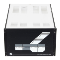
The DIP switches located at the rear of the unit - “INTER-
FACE” - (3/7) must be set to match the respective pump
model; see Table 4.
In addition to the automatic pump identification function,
the pump-specific DIP switch settings also act as a
safety feature. This insures that the pump in question is
protected from mechanical destruction even in the event
of defects in the line cord.
Caution
Do not connect the unit to any TURBOVAC
turbo-molecular pump model that is not
listed in these operating instructions.
Insert the power plug.
Switch on the power switch (3/1).
When the power switch is turned on, all LEDs light up for
approx. 2 s as a function check.
The green LED POWER remains on.
Following this, a self-test is run:
1. check that the line cord is connected,
2. identification of the TURBOVAC model.
Setting the Start-up Delay
You can set a “START”-up delay of up to five minutes at
the rear of the unit at (3/8).
Due to the starting delay the TURBOVAC starts after the
forevacuum pump.
3.2 Start-up of the
TURBOVAC
Pressing the START key initiates the acceleration
sequence; if a forevacuum pump is connected it will start
up immediately.
If a delay has been set, the START LED will flash during
the delay period, after which it will remain on conti-
nuously and the TURBOVAC starts. The acceleration
relay is already active during the delay period.
The NORMAL LED flashes during acceleration. The
LED chain indicates the increasing speed with one LED
each. When 80% of the target speed has been reached,
the LED NORMAL remains on continuously, the START
LED extinguishes.
During normal operation the LED chain indicates the
course of the increasing motor power consumption; the
increasing current (load) drawn by the TURBOVAC is
indicated by the LED chain with one LED each lighting
up after the other starting at the bottom and moving
upwards.
25
GA 05.208/12 - 05/2003
Table 4: DIP switch settings
TURBOVAC Cat. No. DIP switch
1 2 3 4
150, 150 CSV 854 69/70/71/79/80/81, 855 02/03/04/05, 894 10, 895 44 OFF ON ON ON
150 V 856 10/11/12, 894 11 ON ON ON OFF
151 856 30/31/32/35, 894 13 ON OFF ON OFF
360, 360 CSV 854 50/51/56/57/60/61, 855 07/08/09/15, 894 20, 896 67 ON OFF ON ON
360 V 856 20/21/22/23, 894 21 ON ON OFF ON
361 856 70/71/72/73/75/77, 894 23 OFF OFF ON ON
600 856 80/81/82, 894 24/25 OFF ON ON OFF
1000 854 90/91/96/97, 855 35/36/38/39, 894 89/99, 895 89 OFF OFF OFF OFF
1100 894 80* ON OFF OFF ON
* only for NT 20, Cat. No. 857 20
from serial no. Z96 01221
and for NT 20, Cat. No. 857 21
from serial no. Z96 00321
The following DIP switch settings
are not permissible:
ON ON ON ON,
OFF ON OFF ON,
ON ON OFF OFF
 Loading...