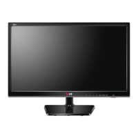
Do you have a question about the LG 24MT45V and is the answer not in the manual?
General guidelines for safe servicing and handling of the receiver.
Procedures to check AC leakage current to prevent electrical shock hazards.
Essential rules for performing TV servicing safely and effectively.
Techniques for handling electrostatically sensitive devices and proper soldering.
Detailed procedures for replacing common components like ICs, transistors, and diodes.
Guidelines for repairing damaged copper patterns on printed circuit boards.
Defines the TV chassis application range and lists general specifications.
Outlines test methods and supported external input signal formats.
Requirements for adjustment, including software version upgrades via USB.
Procedures for EDID download, function checks, and display/sound verification.
Steps for tool option checks, ADC verification, and model/serial number download.
Procedures for verifying TV functions on the production line.
Equipment, notes, and procedures for white balance adjustment.
Procedures for checking software version, DPM operation, and adjustment items.
Flowchart for diagnosing and resolving no power issues.
Flowcharts for diagnosing and resolving no screen or no video problems.
Overall system block diagram.
A visual exploded view of TV components.
Schematics for DC-DC converters and LDO voltage regulators.
Schematic for the panel power control circuit.
Schematics for TV modules, IR/LED control, and IR output.
Schematics for DSUB, RS232C, PC Audio, and Ethernet interfaces.
Schematic for the DSUB and SCART switching mechanism.
Schematics for HDMI inputs and MHL support.
Schematics for Consumer Electronics Control (CEC) and MHL Over Current Protection.
Schematics for the first boost up circuit and panel voltage settings.
Configuration settings for the LED driver based on panel type.
Schematic showing the LCD TV scaler ICs and memory configurations.
Schematics for CI slot interface, detection, and power control.
Schematics for CI Transport Stream input and host interface.
Details for EU Tuner T2/C/S2, including specifications and pinouts.
Schematic for the DVB-S2 LNB power supply circuit.
Schematics for component video input and full SCART connections.
Schematics for the audio amplifier, headphone jack, and detection circuit.
Schematic for the main board, including MCU and memory ICs.
Details on model options and memory configurations for different regions.
| Screen shape | Flat |
|---|---|
| Response time | 8.5 ms |
| Display diagonal | 23.6 \ |
| Display brightness | 250 cd/m² |
| Display resolution | 1366 x 768 pixels |
| Native aspect ratio | 16:9 |
| LED backlighting type | Edge-LED |
| Contrast ratio (dynamic) | 5000000:1 |
| Screen format adjustments | 4:3, 16:9 |
| Supported graphics resolutions | 1366 x 768 |
| 3D | No |
| Tilt angle range | 5 - 20 ° |
| Tuner type | Analog & digital |
| Analog signal format system | PAL, SECAM |
| Digital signal format system | DVB-C, DVB-S2, DVB-T2 |
| RMS rated power | 10 W |
| Number of speakers | 2 |
| DVI-D ports quantity | 0 |
| Common interface (CI) | - |
| USB 2.0 ports quantity | 3 |
| Audio formats supported | AAC, AC3, EAC3, HAAC, MP3, PCM |
| Image formats supported | JPG |
| Video formats supported | DIVX HD |
| Product color | Black |
| Panel mounting interface | 75 x 75 mm |
| AC input voltage | 100 - 240 V |
| AC input frequency | 50 - 60 Hz |
| Power consumption (standby) | 0.3 W |
| Power consumption (typical) | 26 W |
| Package depth | 126 mm |
| Package width | 700 mm |
| Package height | 402 mm |
| Package weight | 5000 g |
| Cables included | AC |
| Depth (with stand) | 166.4 mm |
|---|---|
| Height (with stand) | 392.7 mm |
| Weight (with stand) | 3600 g |
| Depth (without stand) | 56 mm |
| Width (without stand) | 556 mm |
| Height (without stand) | 343.2 mm |
| Weight (without stand) | 3400 g |