EasyManua.ls Logo

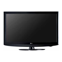
LG 32LH20R-MA Service Manual

LG 32LH20R-MA
30 pages
To Next Page IconTo Next Page
Page #1 background imageLoading...
Page #1 background image
LCD TV
SERVICE MANUAL
CAUTION
BEFORE SERVICING THE CHASSIS,
READ THE SAFETY PRECAUTIONS IN THIS MANUAL.
CHASSIS : LP91A
MODEL : 32LH20R
32LH20R-MA
North/Latin America http://aic.lgservice.com
Europe/Africa http://eic.lgservice.com
Asia/Oceania http://biz.lgservice.com
Internal Use Only

Other manuals for LG 32LH20R-MA

Questions and Answers:

LG 32LH20R-MA Specifications

General IconGeneral
BrandLG
Model32LH20R-MA
CategoryLCD TV
LanguageEnglish

Summary

SAFETY AND SERVICING PRECAUTIONS

General Safety Guidance

General safety guidelines for servicing the receiver.

Leakage Current Cold Check

Procedure for performing the cold check of AC leakage current.

Leakage Current Hot Check

Procedure for performing the hot check of AC leakage current.

SERVICING PRECAUTIONS

General Servicing Precautions

Basic rules and advice for safe and proper TV servicing.

Electrostatically Sensitive Devices

Precautions for handling components sensitive to static electricity.

General Soldering Guidelines

Recommended techniques and standards for soldering.

Component Removal and Replacement

Step-by-step instructions for replacing ICs, transistors, diodes, and fuses.

Circuit Board Foil Repair

Methods for repairing damaged copper traces on circuit boards.

SPECIFICATIONS

Application Range and Product Specs

Defines the scope of the manual and lists detailed TV technical characteristics.

Test Methods

Procedures for testing TV performance and functionality.

Electrical Specifications

Details on power consumption, input voltage, and electrical parameters.

Optical Specifications

Information on display color coordinates, contrast ratio, and luminance.

Input Signal Specifications

Supported video input resolutions and timings.

RGB and HDMI Input Details

Specifics on resolutions and timings for RGB and HDMI connections.

Mechanical Specifications

Physical dimensions, weight, and gap tolerances of the TV.

Panel Gap Measurements

Details regarding specific gap measurements between cabinet parts.

ADJUSTMENT INSTRUCTIONS

Adjustment Scope and Conditions

Defines application range and environmental requirements for adjustments.

Key Adjustment Items

Lists the parameters and items that require adjustment.

PCB Assembly Adjustment Process

Methodology for performing adjustments via software on the PCB.

EDID Data Management

Procedures for downloading and managing Extended Display Identification Data.

ADC Calibration

Process for calibrating the Analog-to-Digital Converter for accurate signal input.

EDID Data Formats

Details of EDID data structures for various input modes.

Input Options and SW Version Check

Setting input modes, options, and verifying software version.

WHITE BALANCE ADJUSTMENT

Overview and Setup

Purpose, principle, required equipment, and connection diagram for white balance.

Manual Adjustment Procedure

Step-by-step instructions for manually adjusting white balance.

White Balance Calibration Cases

Methods for adjusting color coordinates based on target values.

Standard Color Coordinate Targets

Reference values for white balance calibration modes.

TROUBLESHOOTING

Power and Raster Troubleshooting

Diagnostic flows and steps for resolving power and display issues.

Signal Input Troubleshooting

Diagnosing problems related to PC, Component, and HDMI signal inputs.

AV/RF and Audio Troubleshooting

Troubleshooting steps for AV, RF signals, and no sound issues.

SYSTEM DIAGRAMS AND SCHEMATICS

Block Diagram

High-level overview of the TV's main functional blocks and connections.

Exploded View

Visual representation of the TV's internal components and their assembly.

Main Schematic Diagram

Detailed circuit schematics for the primary components of the TV.

DDR2 Memory Schematic

Schematics detailing the DDR2 memory module.

Power Supply Schematic

Circuit diagram for the TV's power supply unit.

Audio Amplifier Schematic

Circuit diagram for the audio amplification stage.

Tuner Schematic

Circuit diagram for the TV tuner module.

HDMI Interface Schematic

Circuit diagram for the HDMI input ports.

Input Connector Schematics

Schematics for various input connectors like Component, AV, S-Video.

PC and USB Interface Schematics

Circuit diagrams for PC input and USB ports.

LVDS and Control Key Interface

Schematics for LVDS display connection and control signals.

Related product manuals